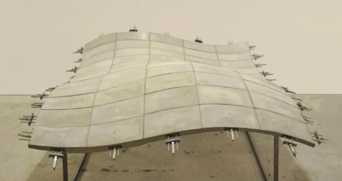
Shells are surface members whose middle surface is not flat but noticeably curved. Their static behavior differs considerably from that of a plate. When they have a suitable shape, their stress is much lower, their stiffness correspondingly greater, and the calculation in most cases simpler.
The stress of every shell can be divided into two parts: membrane stress and bending. Membrane stresses, similarly to the stresses in a plate loaded in its own plane, can be expressed by means of sectional forces in the tangential plane – these are, for example, in the section x=const. the normal force _Nx=_σx*t and the shear force _Nxy=_τxy*t, where t is the shell thickness. The stresses due to bending are the same as for plates and can be represented by bending moments Mx, torsional moments Mxy and shear forces Qx.
The essential characteristics of shells are based on the fact that, as a rule, the stresses due to bending are neither in magnitude nor in significance equal to the membrane stresses, so they can often be completely neglected. In that case, all stresses are evenly distributed over the shell thickness and act tangentially to the middle surface. Calculations based on these assumptions fall within the scope of shell membrane theory.
Membrane theory of rotationally symmetric shells under rotationally symmetric loading
General forms
The meridians and parallel circles on the mid-surface of the shell are taken as coordinate lines, so the coordinates are: azimuth ϑ (“geographical longitude”) and the inclination φ of the tangent to the meridian relative to the plane perpendicular to the axis of symmetry (fig. 1a). Accordingly, the sectional forces are: normal force Nφ in the meridional direction and normal force Nϑ in the hoop direction (fig. 1b). The shear forces Nφϑ do not occur in rotationally symmetric stress. The load per unit area is indicated as follows (fig. 1b): Y tangential to the meridian, positive in the direction in which φ increases, Z normal to the shell, positive toward the axis of symmetry.

Fig. 1

Fig. 2
Let the radius of curvature of the meridian be r1. It is a function of the angle φ, so the equation _r1=r1(_φ) determines the shape of the meridian. This can be regarded as the meridian equation and reads, for example,
for circle r1=a=const.
for the parabola r1=a/cos3__φ
for the ellipse r1=a2b2(a2sin2__φ+b2cos2__φ)-3/2
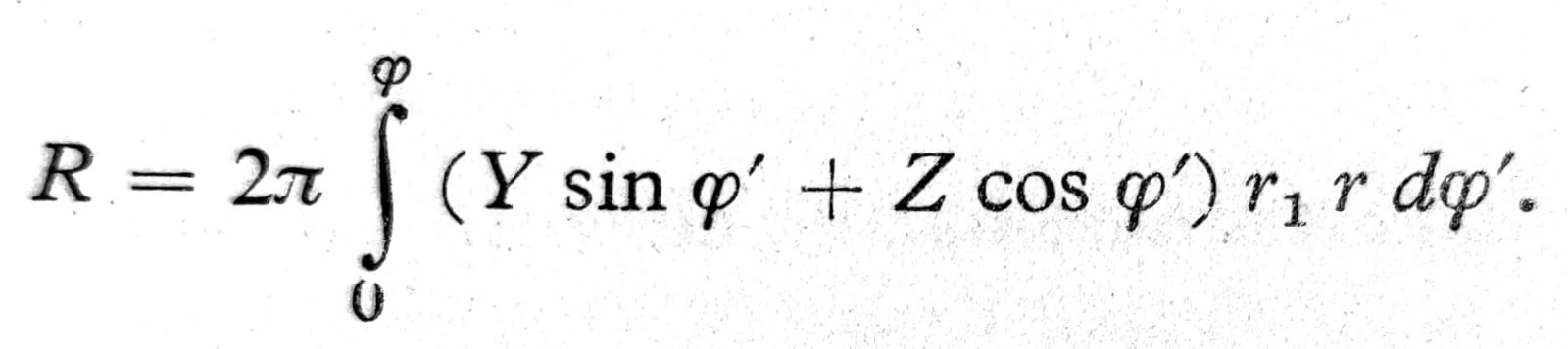
To calculate the normal force N__φ in the meridional direction, the equilibrium condition of the part of the shell lying above the parallel circle φ must be set up (fig. 2). The resultant R of the loads Y and Z acting on this part is vertical, due to symmetry. Its magnitude is obtained by integrating over the shell surface from φ’=0 to φ’=φ. The area of the shell element is dF=r1d__φ’*rd__ϑ, so the vertical component of the load is (Ysin__φ’+Zcos__φ’)dF. For the entire annular part of the shell lying between the circles φ’ and φ’+dφ’ the resultant of the external load is:
dR=2__πr (Ysin__φ’+Zcos__φ’) r1d__φ’,
from which, by integrating over φ’ for the part of the shell lying above the parallel circle φ’=φ, we obtain:
Eq. 1
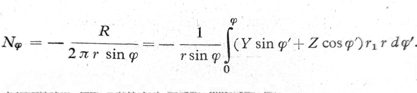
This load is carried by normal forces in the meridional direction, acting along the circumference of the observed circle; the vertical component of the resultant of these forces is 2__πr * N__φ sin__φ, and by equating this the required normal force is obtained
Eq. 2
If the shell at the upper part is cut along the circle φ=φ0 (e.g. an opening for lighting in a dome), the lower limit of the integral is, of course, φ0, not zero. If the load R0 also acts on the edge of the shell thus formed, it too must be added to the resultant R (Fig. 3).

Fig. 3
To determine the normal force N__ϑ, the equilibrium condition of the shell element must be set up perpendicular to the tangent plane (fig. 4). The resultant of the external load in this direction is Z r1 d__φ r d__ϑ. The forces N__φ*r d__ϑ lying in the meridional plane enclose a small angle d__φ with each other, so their resultant in the direction of the normal to the shell is N__φ r d__ϑ*dφ. Likewise, the forces Nϑ r1 dφ lying in the plane of the horizontal circle and forming the angle dϑ with each other have the resultant Nϑ r1 dφ*dϑ, which also lies in the plane of the horizontal circle and therefore forms with the normal to the shell the angle 0,5_π-φ_, so that only their component Nϑ r1 dφ dϑ*sinφ enters the equilibrium condition. The equilibrium condition therefore reads
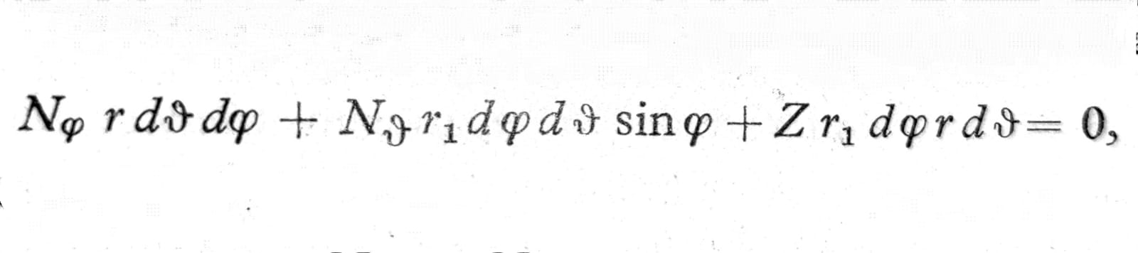
or, when divided by r r1 dϑ dφ:

One. 3
Here r2=r/sinφ denotes the second principal radius of curvature of the shell.
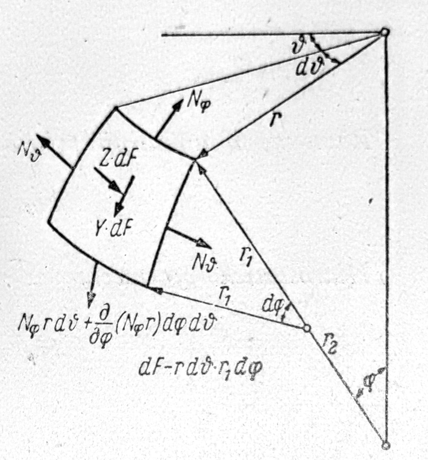
Fig. 4
Circular dome
When the meridian shape is given analytically by the equation r1=r1(φ) and when analytical expressions are given for the loads Y(φ) and Z(φ), the sectional forces in the shell can always be determined by integration in closed form or numerically, using Simpson's rule. For a circular dome of diameter a, the following gives the sectional forces for some loading cases:
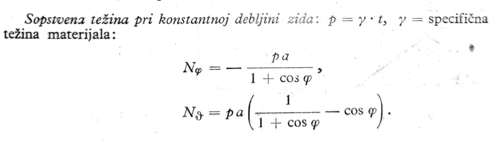
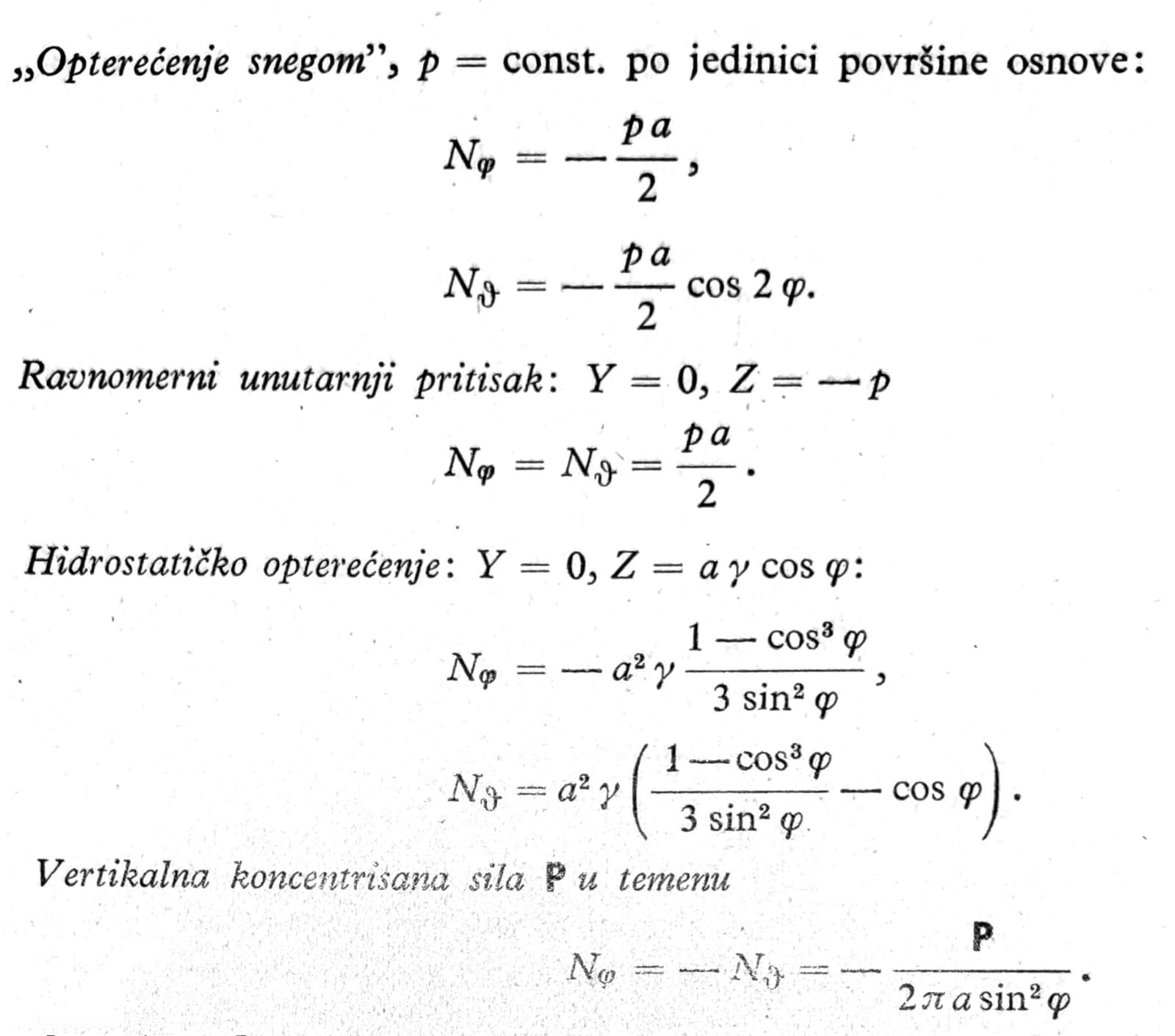
The last formula, which for φ=0 gives infinitely large shear forces, applies only at a certain distance from the point of application of the force. In the immediate vicinity of the point where the force acts, even when it is distributed over the surface of a circle of finite but small diameter, the load is transmitted mainly by bending.
The forms for shells open at the top can be derived from the previous ones if a fictitious load P is added to the actual load at the apex, its magnitude being determined in such a way that the total normal force in the meridional direction acting on the upper edge of the shell φ=φ0 is Nφ=0, or is equal to some value determined by the external forces received by the shell here.
Conical shell

Fig. 5
For a conical shell, the meridian slope φ cannot be used as a coordinate, because it has the same value at all points. Instead, the distance s from the apex of the dome measured along the generator is introduced (fig. 5). The normal force in the meridional direction is accordingly denoted by Ns. The required forms can be obtained from those given under 1 when the limiting transition is performed. From equation (2) one thus obtains
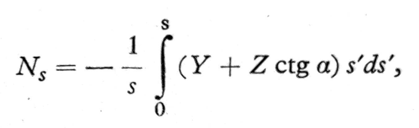
and from equation (3)
Nϑ = -r2 Z = -Z s ctga.
The following formulas apply to the most important loading cases:
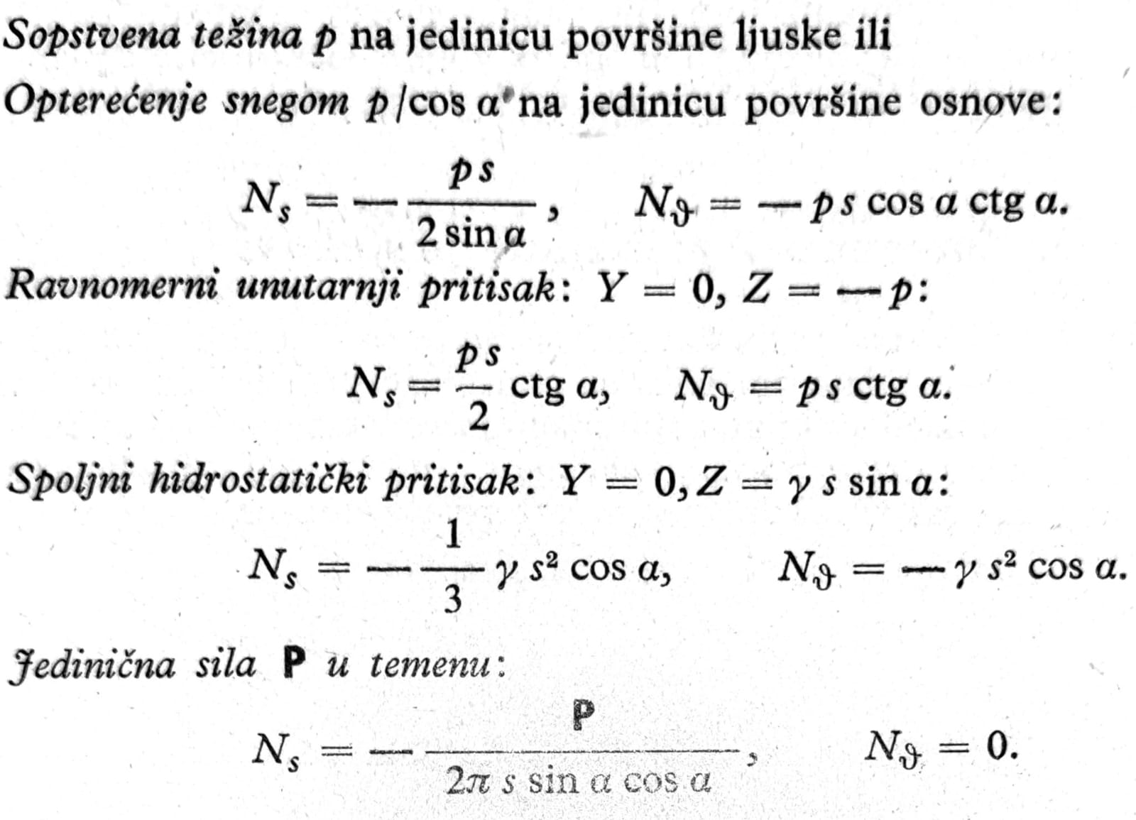
Graphical method for an arbitrary meridian shape
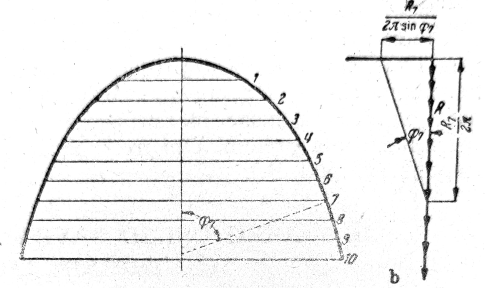
Fig. 6
When the meridian curve is not given by an analytical expression, but, say, graphically, determining the radius of curvature is too difficult and too inaccurate. In that case it is more convenient to use a graphical method (fig. 6).
The shell is divided by a larger number of planes φ=const., the weights Δ_R_ of the annular zones lying between the planes are calculated and it is best to divide them at once by 2_π_. These forces ΔR/2π are plotted in the force diagram (fig. 6b). If then, for example, through the division point 7 a line parallel to the tangent to the meridian at the meridian point 7 is drawn, the horizontal through the upper point of the force diagram will intersect it along R1/2π sinφ7, from which, on the basis of equation (2), by dividing by the corresponding r, the corresponding normal force in the direction of the meridian is obtained.
To determine the forces in the rings, the equilibrium condition of horizontal forces on one shell element is used. If only vertical loads act, this condition reads (fig. 4):
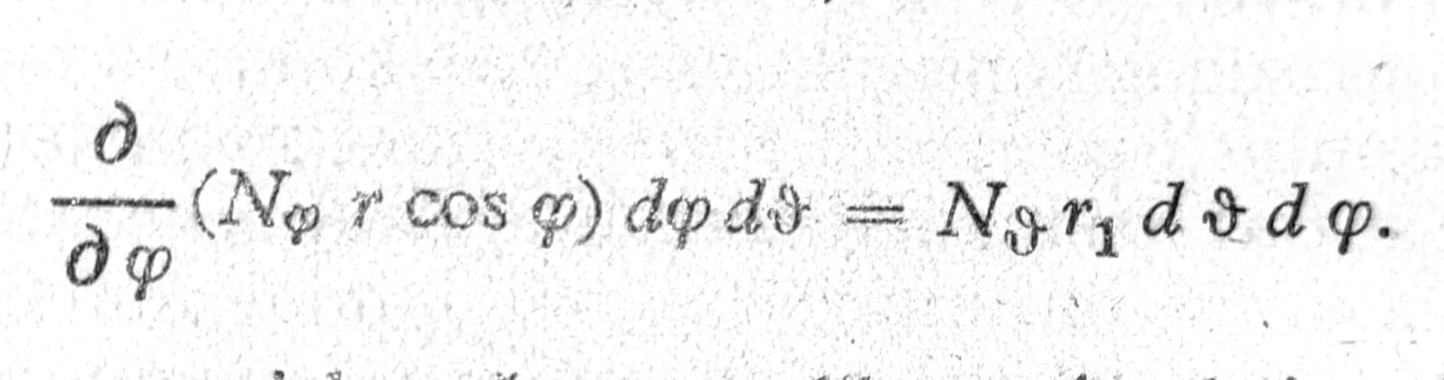
When here dφ is replaced by the finite difference Δφ, corresponding to the adopted division of the shell, and when the length Δs of the meridian element is introduced instead of r1 dφ, one obtains
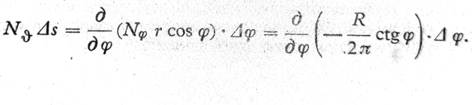
In the bracket on the right there is a segment on the horizontal line in the force diagram. The entire right side therefore represents the segments between the division points on this line. In order to read them with sufficient accuracy, the force diagram must be drawn carefully and at a sufficiently large scale.
Tensioned and compressed rings
Every rotationally symmetric shell is bounded by one or two horizontal circles (fig. 7). At these edges, in principle, it can receive only such loads and support reactions that are directed along the meridian tangent. If the external forces have a different direction, such as the load P from the upper part of the structure or the reaction S of the bottom of the reservoir shown in fig. 97, these forces must, as shown in the figure, be resolved into components in the direction of the horizontal circle and the meridian tangent. The component P/sinφ0 or S/sinφu is equal to the normal force in the meridian direction Nφ acting at that point, while to receive the horizontal force Pctgφ0 or Sctgφu a ring is required that takes tension, respectively compression, and in which this radial load causes the normal force + P r0 ctgφ0, respectively -S ru ctgφu. Such rings must be placed, in addition to the shell edges, also at all those places where the meridian curve has a break. They always cause a disturbance of the membrane stress state.
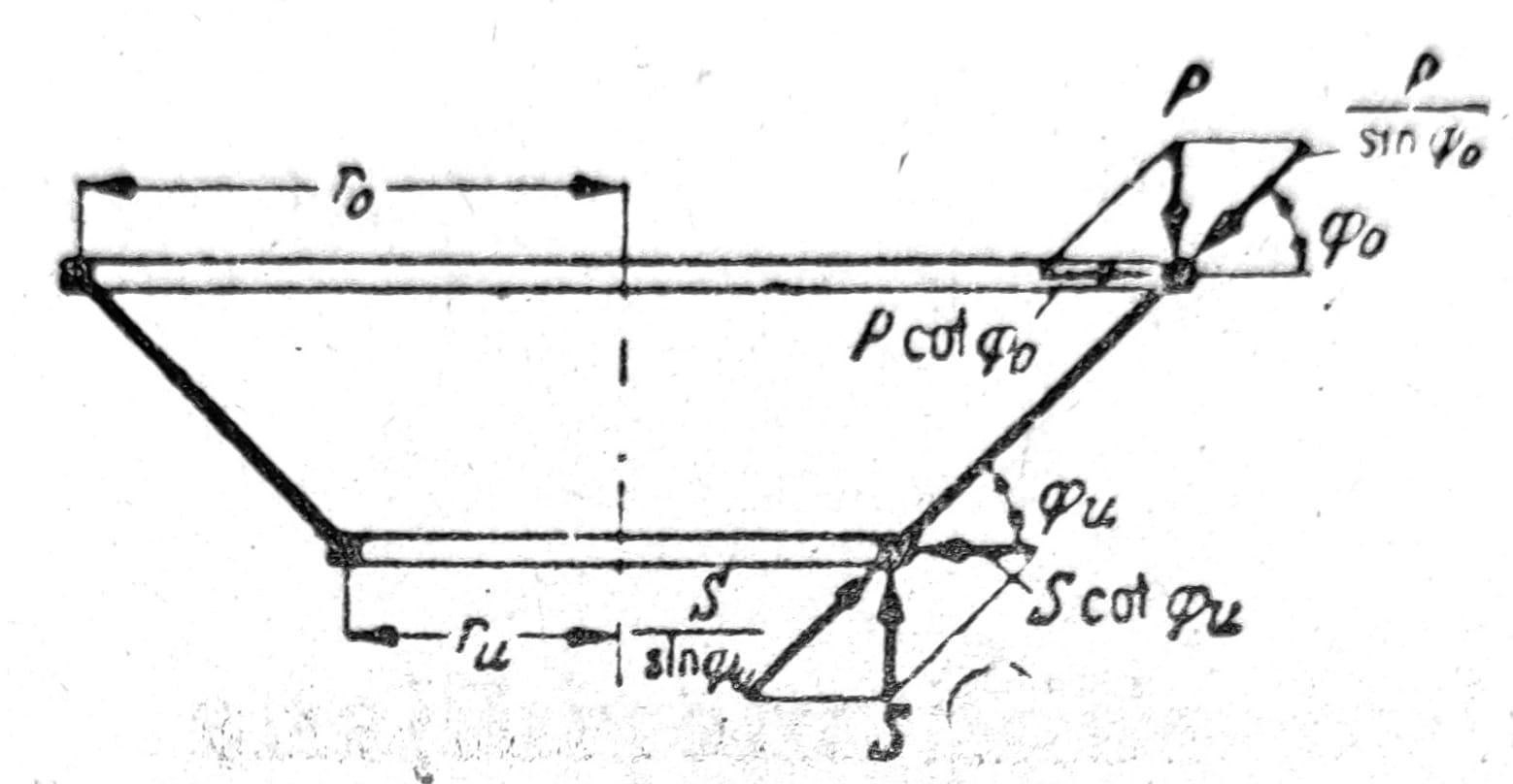
Fig. 7
Stresses due to bending in rotationally symmetric shells
The forms of membrane theory do not contain a sufficient number of integration constants for all the boundary conditions that actually correspond to the given problem to be satisfied. In particular, for rotationally symmetrical shells, it is not possible, by any suitable choice of integration constants, to make the strain εϑ = Nϑ/Et in the circumferential direction along the shell edge equal to the corresponding strain of some other structural part rigidly connected to it at that point. The same applies to shells in which the meridional curvature, shell thickness, or load per unit area changes abruptly along a horizontal circle. Even when a shell is not stiffened by a ring along an edge, but is loaded at this location by forces that have a component in the direction of the normal to the shell (e.g. load P in fig. 7 when the ring is imagined to have been removed), it cannot carry such loads through membrane forces alone. In such cases, shear force and bending moments (fig. 8) play an essential role in the distribution of forces in the shell, which must be taken into account in the static calculation.
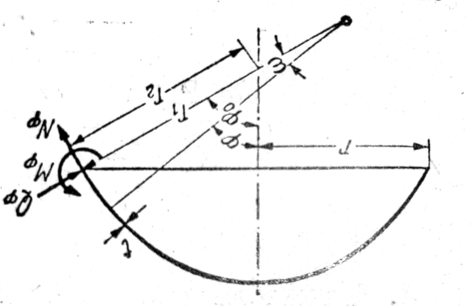
Fig. 8
An exact calculation of a shell in bending, except in the simplest special case of a cylindrical shell, is a very difficult task. For thin-walled shells, a simple and very useful approximate theory can be developed based on the fact, known from the rigorous theory, that bending stresses are confined to a relatively narrow zone near the edge and decrease rapidly as the distance from the edge increases. This makes it possible to neglect a large number of terms in the exact differential equation, and it then takes on a simplified form.
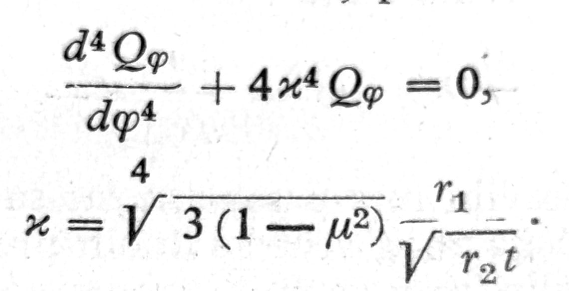
If within the edge zone, which is the only zone of interest κ, it is replaced by the mean value, and this is almost always possible, the solution of the equation is
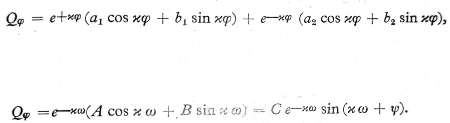
No. 4 and 5
where a1, b1, a2, b2 are integration constants. Since the solution is of interest only in the vicinity of the edge φ=φ0, it is convenient to introduce the angular distance ω=φ0-φ or ω=φ-φ0 from this edge as the coordinate, and by transforming the above solution the other expression given is obtained. Here only two integration constants A, B or C, ψ appear, since the second part of the solution containing the factor eκω, and therefore not decreasing with increasing ω, can be excluded from consideration.
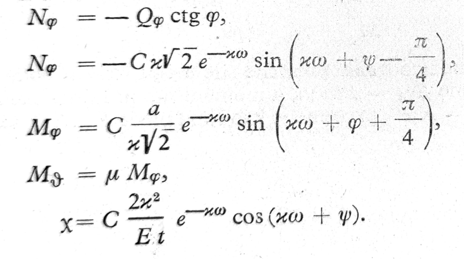
Based on equation 5, the following values are obtained for the sectional forces and the rotation of the meridian tangent κ:
Bending stresses in cylindrical reservoir-shaped tanks
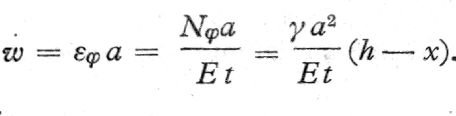
Let a cylindrical reservoir of height h be filled with water (fig. 9), then at a height x above the reservoir bottom the water pressure is p=γ(h-x). If, at this height, a ring is cut from the reservoir by two horizontal sections spaced dx. and this ring is split along one diameter into two parts, the equilibrium condition of one of them gives the membrane force in the ring Nφ=pa. If the thickness of the reservoir at this point is t, the strain in the ring is εφ=Nφ/Et and therefore the increase in the reservoir radius (deflection) is
At the lower edge x=0 it is therefore
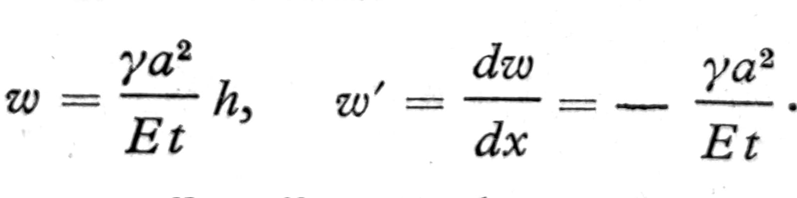
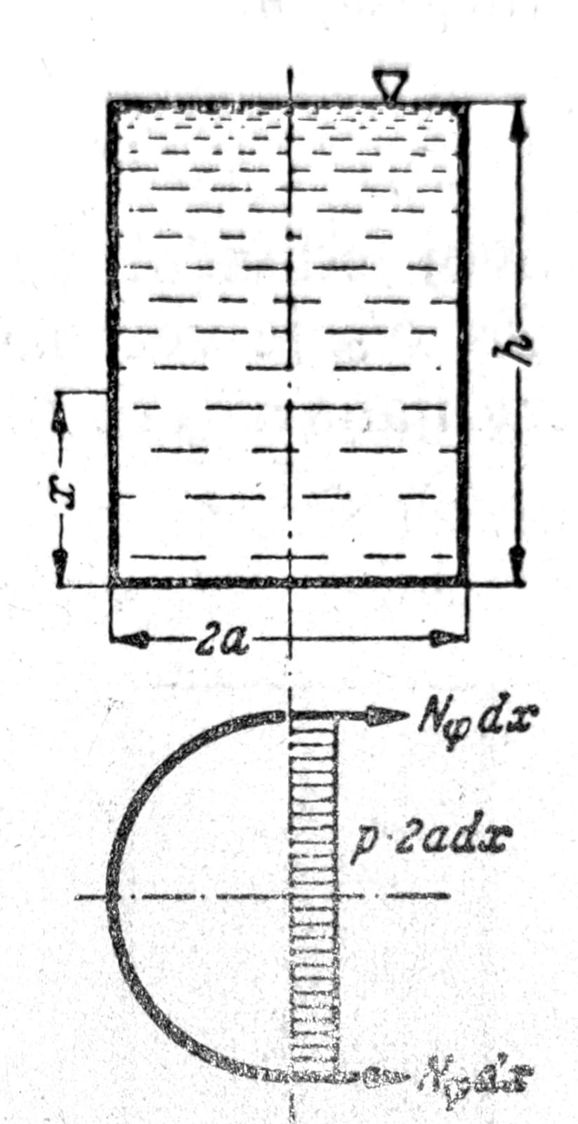
Fig. 9
Neither one nor the other is, as a rule, in accordance with the boundary conditions, because deformation of the wall is prevented by its connection to the tank bottom. At the connection between the bottom and the cylindrical wall, transverse forces Qx0 and moments Mx0 appear (fig. 11), whose magnitude should be determined so that together with the membrane forces just calculated in the shell they cause this deformation at the edge of the shell permitted by the bottom.
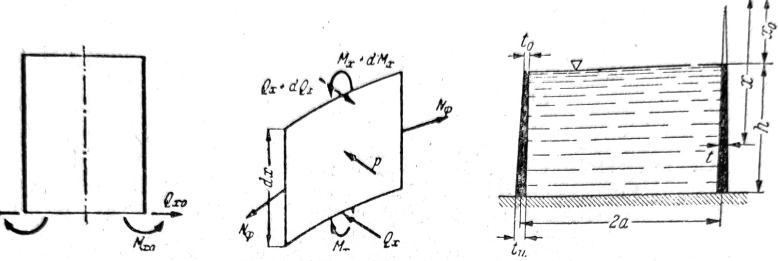
Fig. 10, 11, 12, respectively
In fig. 11 an element of the shell dx*a dφ with the forces acting on it is shown. The condition of force equilibrium in the direction normal to the shell gives
dQx a dφ + Nφ dx dφ = p a dφ dx,
from which, by dividing by dx dφ:
a Q’x + Nφ = p a.
From the condition that the moment about the horizontal tangent to the cylinder is zero, we obtain:
dM/dx = M’x = Qx
By eliminating the transverse force Qx from these two equations, it follows
a M’’x + Nφ = p a.
Eq. 6
In this equation, these unknown transverse forces can be expressed in terms of the deflection w. For Nφ, it has already been found that Nφ=Etw/a, and the moment is proportional to the meridian curvature w’’, i.e. Mx=Kw’’, where, as for plates, K=Et3/12(1-μ2) is the shell stiffness, which may vary with x. If these expressions for the average forces are substituted into equation (6), the differential equation of tank theory is obtained:
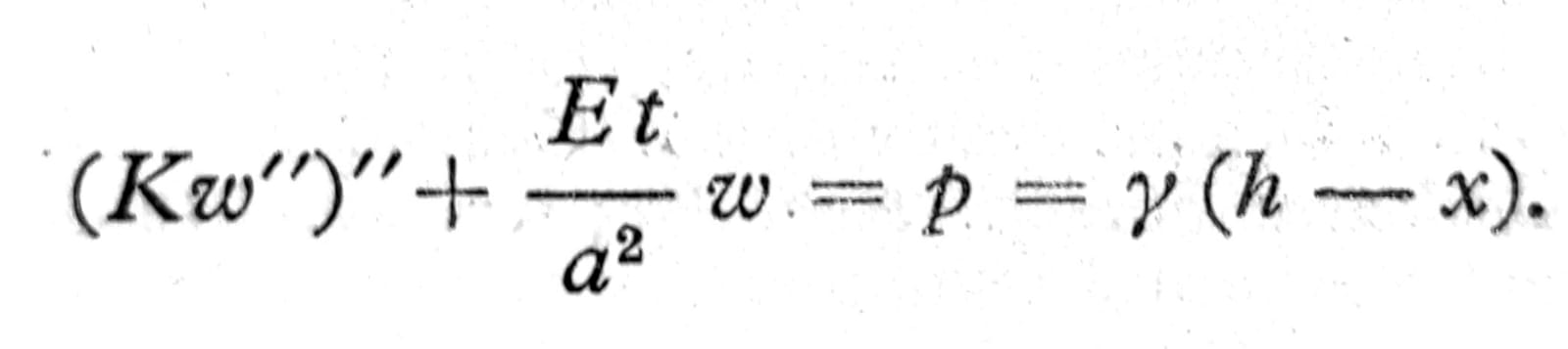
For a tank with constant wall thickness, the solution is:
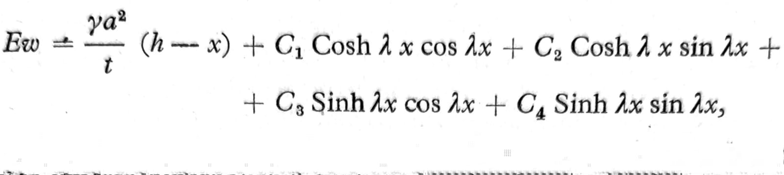
One. 7
where λ4=3(1-μ2)/a2t2. If λh is large (say, greater than 3), it is more convenient to introduce exponential functions instead of hyperbolic functions, so that:
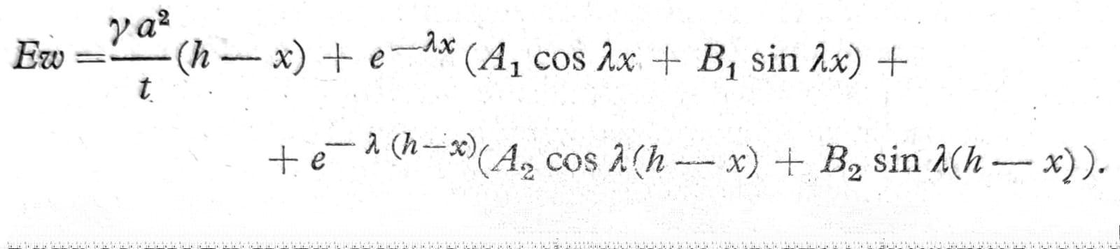
One. 8
Then the constants A1, B1 can be determined independently of one another from the boundary conditions at the lower edge, and the constants A2, B2 from the boundary conditions at the upper edge, whereby as a rule A2=B2=0 is obtained. From equations (8) and (7) the shear forces are obtained, when the calculation is carried out in the reverse direction and equations (8) and (7) are introduced everywhere; thus, for example, for A2=B2=0:
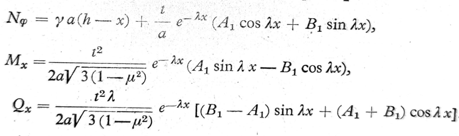
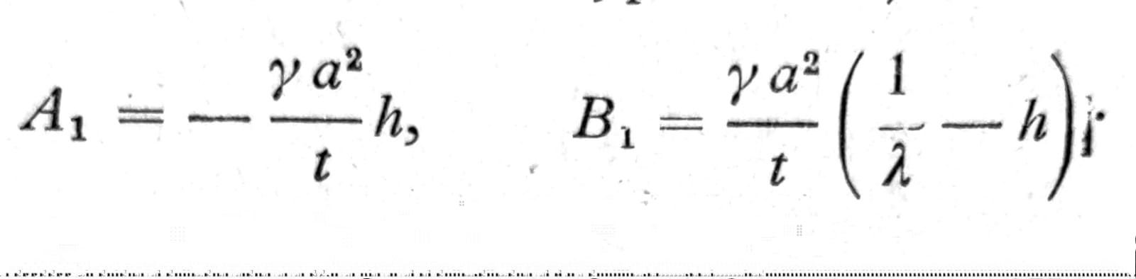
When the tank walls are rigidly fixed into the plate, on the bottom of the tank, which is thick enough to be considered rigid, the constants A1, B1 should be determined from the conditions that x=0, w=0 and w’=0, yielding:
If the bottom of the tank is an elastic plate or shell, the transverse forces Qx and moments Mx along the peripheral circle between the bottom and the cylinder wall should be determined by the methods of the theory of statically indeterminate systems on the basis of the requirement that Mx and w’ for both parts have the same value.