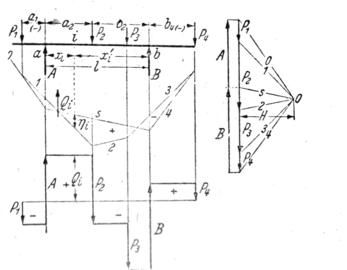
Important professional and safety note: This is an archival educational text, not a static calculation, construction project or instruction manual. Formulas, support models and drawings were transferred from the original content without professional verification or adaptation to today’s regulations. The bearing capacity, stability, loads, materials, joints and foundation for a specific object must be determined by a certified civil engineer based on valid standards, geotechnical data and the actual condition of the structure. The illustrations are educational and do not represent confirmed projects of Savo Kusić.
Static calculations and design of supporting structures are not part of the company’s new public offer. The current production focus consists of wooden חלונות, wooden-aluminum חלונות and custom-made doors. For a specific window or door project, you can send request for quote.
Structure and division of supports
Support elements: internal and external stability
Elements of the support are:
מוטות פשוטים המסוגלים להעביר רק כוחות מתיחה או לחיצה שקו ההתקפה שלהם חופף לציר המוט. זה מצריך שהמוטות בקשרים יהיו קשורים במפרקים ללא חיכוך, ושכוחות חיצוניים יתקפו את הקשרים. תומכים המורכבים רק ממוטות פשוטים נקראים מסבכים.
Sticks resistant to bending - beams - can transmit both forces whose lines of attack coincide with the axis of the rod, and forces whose lines of attack are parallel to the axis of the rod or arbitrarily inclined to it. Beams receive normal forces, transverse forces, bending moments and, in the given case, torsion moments. Those in knots can be tied with hinges or with rigid angles.
Supports and clamps prevent the support from moving towards fixed points in the plane or space. Each support is capable of transmitting a force in a certain direction that passes through the suspended node. If there is only one support in the supported node - support point - it is called a movable bearing of the spatial support. If the node is supported by two supports, it is called a immovable bed of a flat support, or space carrier line bed. The stationary bed of the spatial support requires three supports.
Each pinching of a bending-resistant rod is able to transmit a pinching moment lying in a certain plane. ברוב המקרים מחברים מיסב בלתי מזיז למהדק, כך שבמשענת שטוחה יש שני תומכים ומהדק אחד, ובמשענת מרחבית יש שלושה תמיכות ושלושה מהדקים. Movements and rotations of a certain size can occur at places of support and pinching.
המספר הנדרש של אלמנטים ליציבות התמיכה מתקבל מהתנאים ליציבות פנימית וחיצונית. התמיכה יציבה פנימית כאשר המיקום הבין-חדרי של צמתי התמיכה מובטח על ידי מספר מספיק של מוטות כך שניתן לשנותו רק כאשר חלק מהמוטות או כולם משנים אורכים. תמיכה שטוחה יציבה פנימית נקראת לוח נוקשה. התמיכה היא חיצונית או יציבה לחלוטין כאשר מיקום הביניים של הצמתים ומיקומם בהתאם לנקודות הקבועות של המישור, או החלל יכולים להשתנות רק במידת השינויים באורך המוטות, תנועת התומכים או סיבוב ההידוק.
סוגריים שטוחים
The minimum number of rods required for internal stability and the minimum number of rods and supports required for external stability of a truss with s rods, a supports and k nodes is:
s = 2k – 3
s + a = 2k, (3 ≤ a)
The first condition is fulfilled when the support is formed starting from one rod by connecting further nodes with two rods each, whereby the rods to which one node is attached must not lie on the same straight line.
The beam with s1 simple rods, s2 bending-resistant rods, e rigid angles, a1 supports, a2 clamps and k nodes is internal, resp. יציב חיצוני כאשר:
s1 + s2 + e ≥ 2k – 3
s1 + s2 + e + a1 + a2 ≥ 2k, (a=a1 + a2 ≥ 3)

איור. 1
Each solid angle can be replaced by a simple rod. If in one node i rods are rigidly connected to each other, the number of rigid angles in that node is i-1. When the overhangs of the rods (consoles) are counted as rods, the free ends should be counted as nodes. The bracket in fig. 1 with s1=9, s2=7, e=5 (marked in the picture) and k=12 is internally stable. When we replace the rigid angles 4 and 5 with joints and simple rods, which are marked with dashed lines in the picture, then s1=11, s2=7, e=3, while the number of nodes remains unchanged.
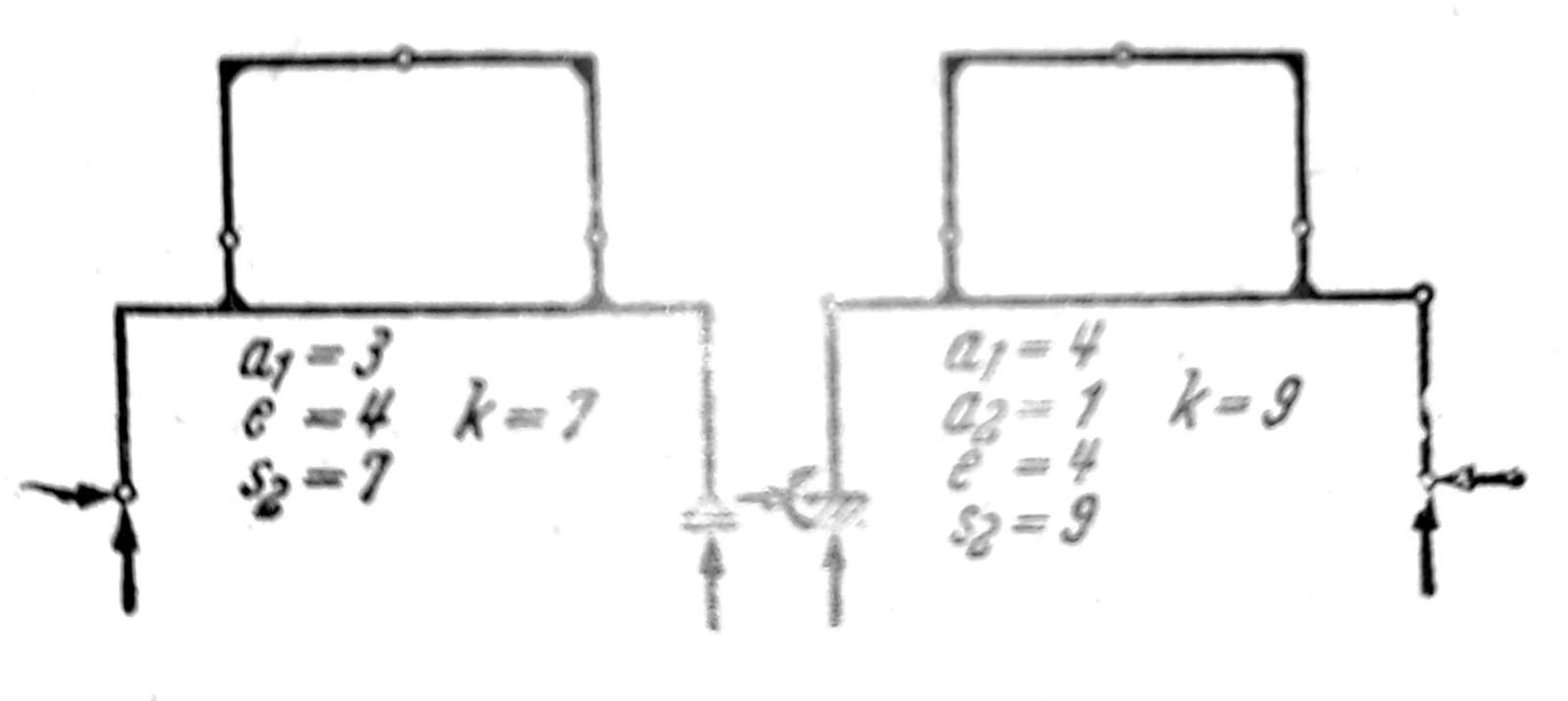
Fig. 2a ו-2b
If in one support with the required minimum number of supports, individual rods or rigid angles are replaced by supports or clamps, the support loses its internal stability, fig. 2a, b. For such supports there are other possibilities of how stability can be tested. If p is the number of rigid plates of the support without internal stability, while it should be noted that a single simple rod or rod resistant to bending meets the conditions of internal stability and can be understood as a rigid plate, and if z is the number of intermediate reactions in the joints, the external stability requires that: a + z ≥ 3p. The number of intermediate reactions in the joint where the plate is attached (fig. 3, 4, 5) is z=2(_i-_1).
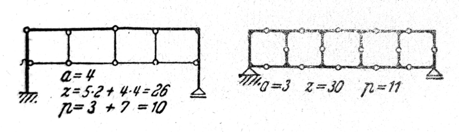
Fig. 3 and 4, respectively

Fig. 5
Frame in fig. 6 is statically indeterminate six times. If the overhangs, which have no influence on the degree of static indeterminacy, are counted as rods, the rigid angles with which they are attached to the system should also be taken into account and the free ends of the overhangs should be counted as nodes (s=7, e=6, a=9, k=8). In the case of these types of supports, the appropriate form of conditions for internal and external stability testing is:
3_s_ ≥ 3k-3; 3s+a ≥ 3k, (a≥3).
At the same time, passes must not be counted in sticks. Often, in such cases, the fastest way to come to a conclusion about the degree of static indeterminacy of the support is by cutting the rods or excluding static quantities until an undoubtedly stable, statically determined support remains. עם שלושת הסעיפים המצוינים באיור. 7 three static quantities are excluded (normal force, transverse force, bending moment).
If in one n0-times statically indeterminate flat lattice all rods in the nodes are rigidly connected, the degree of static indeterminacy is
n = n0 + 2s – k.
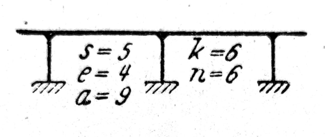
איור. 6

Fig. 7
סוגריים רווח
The minimum number of supports for spatial grids is a=6. The following conditions apply to internal and external stability:
s ≥ 3k – 6; s + a ≥ 3k, (a≥6).
The condition for internal stability is met when, starting from one triangular plate, further nodes in the space are connected with three rods each, which must not lie in one plane. In this way, a spatial lattice of the first kind is created, the characteristic of which is that it always contains at least one node in which only three rods are tied, and that it retains this feature even when that node with the corresponding rods is removed.
Furthermore, spatial grids can be formed by connecting triangular plates in such a way that two and two plates are connected with six rods, where each node is connected to the adjacent plates with two rods each. The connection of two plates or two internal stable spatial grids can be realized by means of one joint and three rods that do not pass through that joint. Finally, three triangular plates can be connected with 12 rods, with one 4 rod between each plate. For internal, or the external stability of spatial supports where all rods are rigidly tied to bending and twisting, the conditions
6s ≥ 6(k-1); 6s + a ≥ 6k
לכן, התושבת באיור. 8 is 24 times statically indeterminate, which, as before, can be most easily verified by cutting four horizontal bars and thus excluding six unknowns in each section (1 normal force, 2 transverse force, 2 mbending moment and 1 torsional moment). If we remove f connections by inserting joints in rods or their connections, then the stability conditions are:
6s – f ≥ 6(k-1); 6s – f + a ≥ 6k.

Sl. 8
Load and reactions: statics tasks
For flat supports, the external forces must lie in the plane of the support, for spatial supports they can have an arbitrary position. With trusses, it is assumed that the load attacks at the nodes.
כוחות פעילים גורמים להתנגדויות של אלמנטים חיצוניים, תגובות של תומכים C בתומכים ורגעי צביטה E בצביטה. ההתנגדויות של האלמנטים הפנימיים של התומך - כוחות החתך - הם: כוחות צירים S במוטות פשוטים; במוטות עמידים בפני כיפוף ופיתול כוחות נורמליים או אורכיים N, מומנטי כיפוף M, מומנטי פיתול או מומנטים פיתולים T וכוחות רוחביים Q. ההתנגדות של האלמנטים יכולה גם לגרום לשינויים בטמפרטורה והתרופפות התומכים.
Dimensioning of individual elements and determining the voltages that appear in them is the task of Material Resistance. When determining the static values, the applied material is important only to the extent that the permanent load depends on it. Other properties of the material are taken into account only when it comes to the influence of support movement or temperature changes (shrinkage, flow) or when deformations need to be calculated. In general, girders should be tested for various load cases that do not have to occur simultaneously (permanent load, useful load, wind load, snow load). Assuming that the elastic deformations are so small that they can be ignored in relation to the dimensions of the system - and this is usually the case - the principle of superposition applies, according to which individual load cases and other influences may be examined separately and the calculated values for static or geometric quantities added together, with a certain correction of the values through partial safety coefficients for permanent and variable loads (favorable or שלילי).
Statically determined supports
Unknown and available equations
בסריג שנקבע סטטית, תגובות a של התומכים והכוחות הציריים s אינן ידועות, אשר קביעתם זמינה כאשר לסריג יש k צמתים2משוואת k (∑X=0ו- ∑Y=0) במטוס i3משוואת k במרחב. בתמיכה שטוחה, ניתן לצמצם את הבלתי ידועים ל-s1 של כוחות צירים של מוטות פשוטים, s2 כוחות נורמליים של מוטות עמידים בפני כיפוף, e רגעי כיפוף בזוויות קשיחות, a1 תגובה של תומכים ו_a2_ רגעי הידוק. יש לקבוע את הכוחות הרוחביים מהמומנטים בקצות המוטות והכוחות החיצוניים הפועלים בין הצמתים. בצומת שממנו מתחילים i מוטות מחוברים נוקשים לצמתים השכנים, מספיק לדעת i-1 mאות - שמתאים למספר הזוויות הקשיחות - כי לקביעת מומנט לא ידוע נוסף בכל צומת כזה יש מצב שיווי משקל ∑M=0. כדי לקבוע s1 + s2 + e + a1 + a2עדיין נותרו _ לא ידועים2_k תנאי שיווי משקל.
תנאים לאיזון כוחות חיצוניים על תומכים שטוחים
תגובות של תומכי לוח הנשענים על מיסב אחד קבוע ואחד נע (איור.9) מתקבלים בצורה גרפית באמצעות מצולעי כוח. קו ההתקפה של כוח B ידוע ויש לו את כיוון התמיכה באותה נקודה, וקו ההתקפה של כוח Ka חייב לעבור בצומת הכוחות B ו-P. הוא מחושב מהתנאי Ma =0, H =0ו-Mb =0נקבעים בהדרגה על ידי הכוחות B, C ו-A. הנחת הצלחת על שלושה מיסבים נעים (איור.10) נכון רק כאשר קווי התגובה אינם מצטלבים בנקודה אחת. התגובות נקבעות בצורה גרפית באמצעות מצולעי כוח או חישובית באמצעות משוואות מומנטים ביחס לנקודות שבהן שניים ושני קווי תקיפה של כוחות מצטלבים.
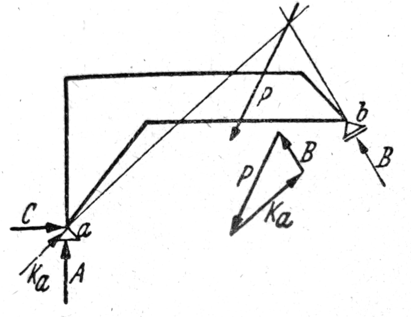
Sl. 9
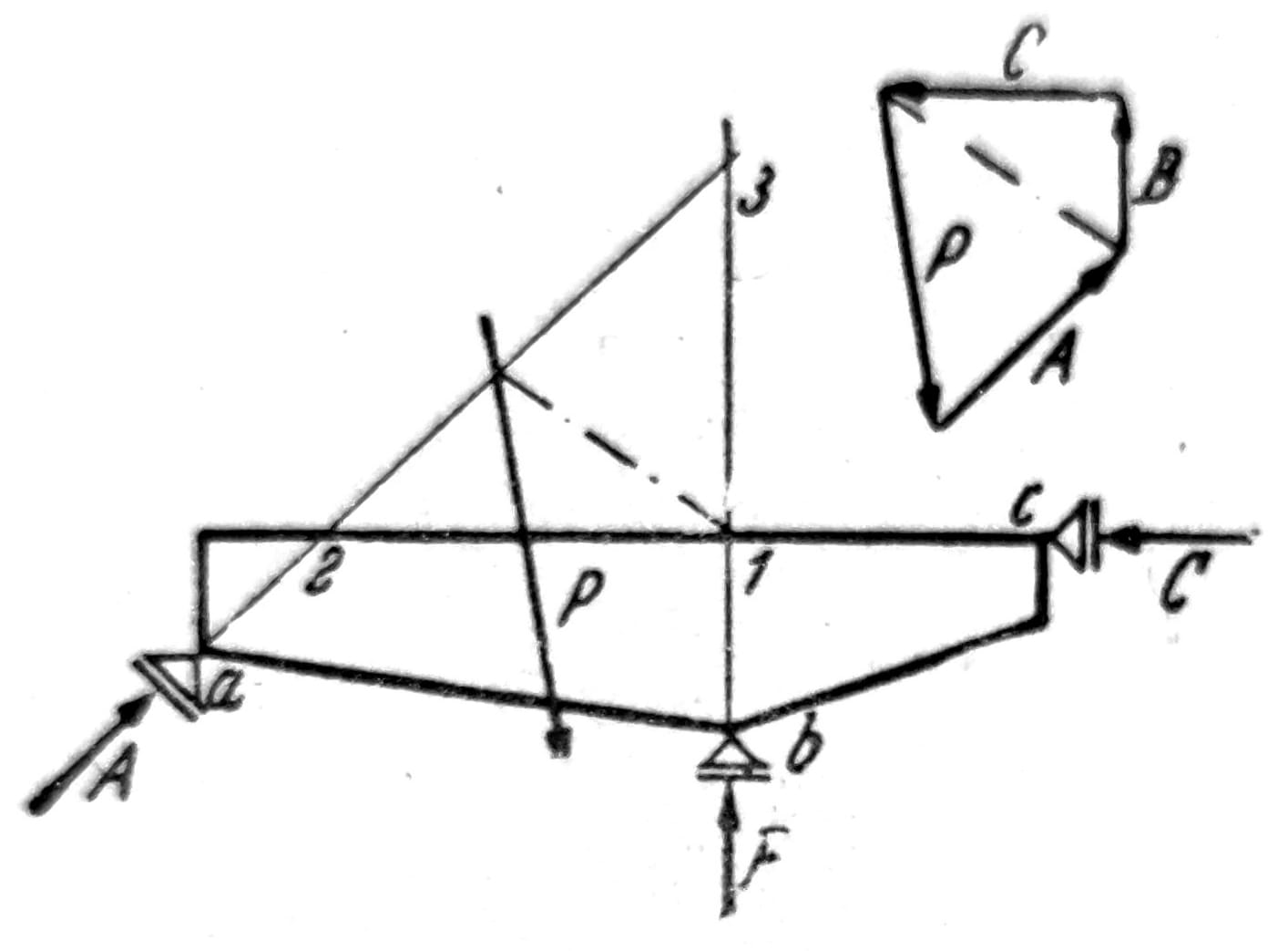
איור. 10
In case of statically determined supports without internal stability, in addition to the conditions for the balance of external forces as a whole, conditions for the joints are also introduced, which express the requirement that the joints cannot receive bending moments. Therefore, the attack line of reaction Ka of the three-hinged frame in Fig. 11 mora passes through the joint g, and the right plate can be in equilibrium only when the three forces acting on it (P, Kb and force in the joint = Ka) intersect at one point. In order to obtain equilibrium conditions containing only one unknown each, it is convenient to calculate with the vertical components of reactions A and B and components C and D along the line connecting the support points. From the conditions Mb = 0 and Ma = 0, forces A and B are obtained, and from the condition for the joint Mg = 0, for the forces attacking the left plate, force C is obtained, and for the forces on the right plate, force D. In a similar way, the reactions of the frame supports are determined in fig. 12. For the load given here, the fastest way to get the result is graphically. סוגר עם חיבורים לפי איור. 13. The horizontal components of the external forces that attack the support are received by the stationary bed, the force F is obtained from ∑H=0. Plate II rests at points g1 and g2 on plates I and III, and plate IV at g3 on III. The vertical forces in the joints G1, G2, G3 and the reaction E are determined from the equilibrium condition of the plate II or IV, and then step by step the reactions A, B, C and D are determined.
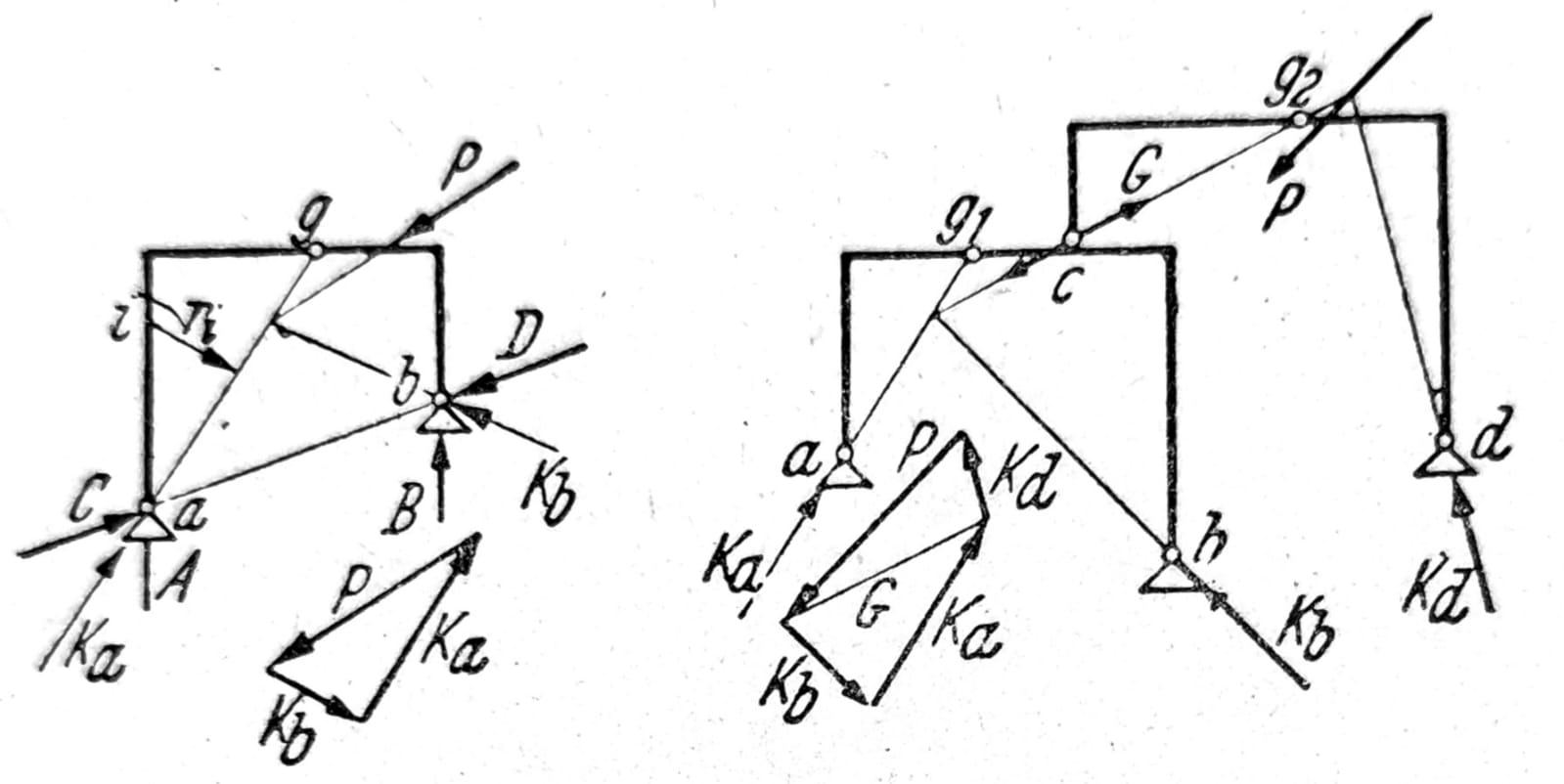
Fig. 11 and 12, respectively

איור. 13
Determination of internal static sizes
כוחות צירים S של מוטות פשוטים נחשבים, ככלל, חיוביים כאשר הם כוחות מתח, ושליליים כאשר הם כוחות דחיסה. In a similar way, the sign of the normal force N in the beam is determined. הכוח הנורמלי Ni בנקודה i הוא הרכיב המקביל למשיק לציר הקורה בנקודה i של התוצאה R של כל הכוחות הפועלים על הקורה בצד אחד של הנקודה i. הכוח הרוחבי Qi הוא הרכיב הנורמלי לציר המוט בנקודה וזהה והתוצאה, ומומנט הכיפוף Mi הוא מומנט התוצאה (איור 14). קביעת הכמויות N, Q ו-M נעשית באופן קבוע מכוחות בודדים ומרכיביהם מקבילים ומאונכים לציר המוט מבלי לקבוע את ה-R המתקבל. The convention of positive directions is shown in fig. 15.
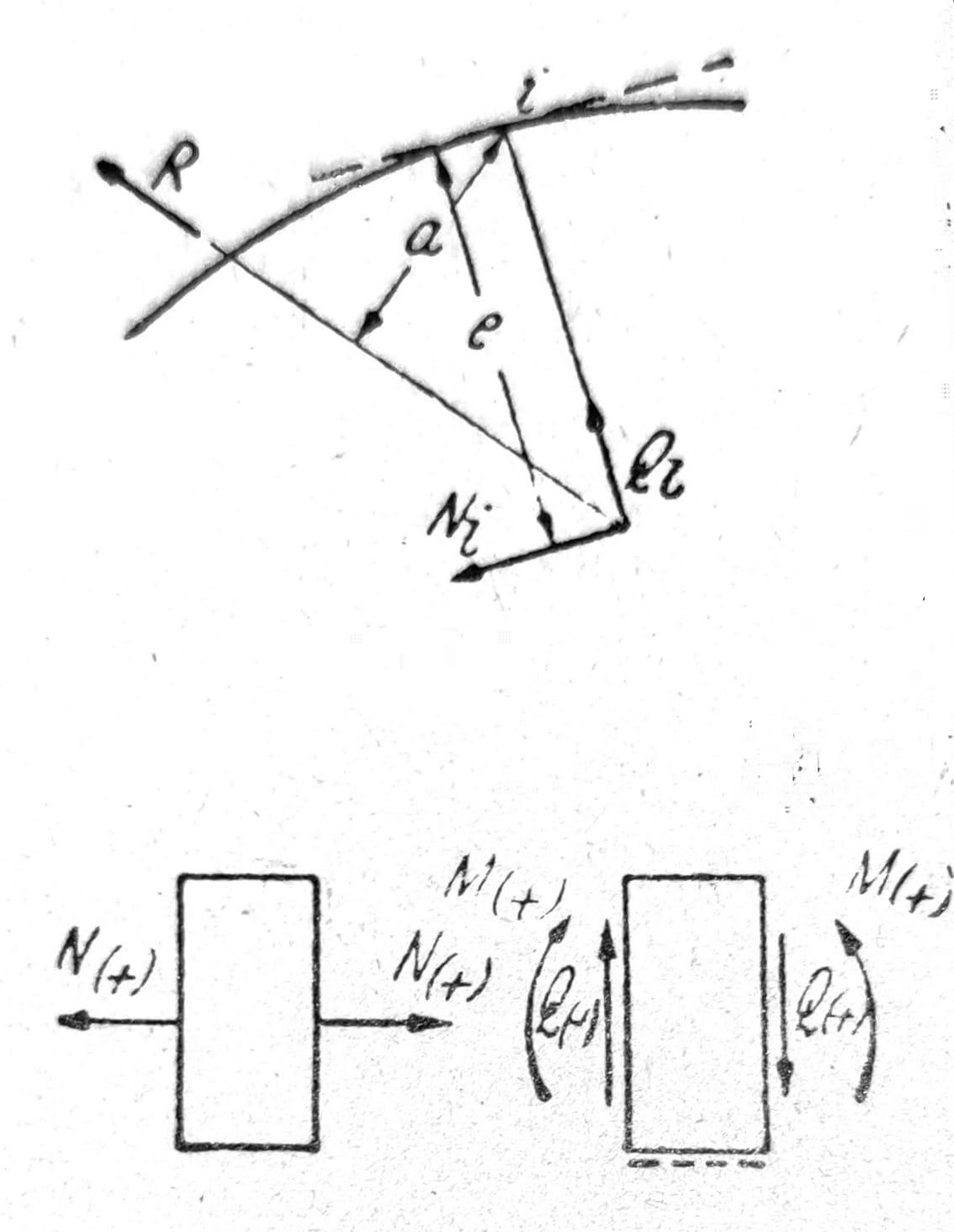
Fig. 14 and 15, respectively
מכיוון שתגובות התמיכה נקבעות בצורה גרפית, ניתן לקבוע כוחות נורמליים, מומנטי כיפוף וכוחות רוחביים ממצולע הכוח ומהתכנית שבה הכוחות ניתנים לפי מיקום. For example, in the left column of the three-hinged frame in fig. 11 הרכיב האנכי של הכוח Ka הוא הכוח הנורמלי (שלילי), הרכיב האופקי הוא הכוח הרוחבי (שלילי), ו-Mi = Kari מומנט הכיפוף, שלילי כאשר מומנטים הגורמים למתח בפנים נחשבים חיוביים.
In every node where the rods are hinged, the conditions ∑X=0, ∑Y=0 must be met. Grids that are formed in the simplest way - by connecting nodes with two rods each - always have at least one node where only two rods meet. By removing such nodes, this feature is maintained. Calculation of axial forces in rods can be carried out by gradually solving two equations with two unknowns each.
The graphic solution is obtained by constructing a force plan (Cremana plan) according to fig. 16. The external forces P1 to P6 are in equilibrium. הכוחות במוטות Si נקבעים בהדרגה החל מהנקודה 1 ועוברים מצומת לצומת בסדר שהם מסומנים. Marking of forces is also done in the order in which they are determined. Each node corresponds to a polygon of forces with a continuous arrow direction, from which the signs of the forces in the rods follow. אם נעשה חתך דרך התמיכה ואם במקומות בהם חותכים את המוטות מופעלים הכוחות הפועלים במוטות אלה ככוחות חיצוניים, כל חלק של הסריג נמצא בשיווי משקל. על זה, נרשם הנוהל של Culmann, שבאמצעותו ניתן לקבוע את הכוח במוט שרירותי באופן גרפי בלתי תלוי בכוחות אחרים.

Fig. 16
In the analytical solution of the problem of setting equations with one unknown, Ritter’s procedure is of greatest importance. The lattice is cut so that three sticks are affected by the cut. The forces in the section bars are applied to each part of the truss as tension forces, from the node to the section. Equilibrium conditions apply to each part of the lattice. The intersection of two and two intersecting rods is the moment point when determining the force in the third rod (Ritter's point). אם ri הוא המרחק של הכוח Si מנקודת הרגע i, ו-Mi הוא מומנט הכוחות הפעילים והתגובות של התומכים ביחס לנקודה i, אז הכוח במוט ניתן על ידי הביטוי
Si = _± Mi/ri

איור. 17

Fig. 18
לפי איור. 17 and 18 forces in cross-sectional rods are:
On = -Mn/rn; Un-1 = Mn-1/rn-1;
Dn = Md/rd; Ln = Mv/rv.
כאשר הבנייה הגרפית אינה מספקת דיוק מספיק, יש לחשב את המיקומים של נקודות הרגע d ו-v והמרחקים rd ו-rv. לחישוב הכוחות D ו-L מתאימים יותר הביטויים הבאים, שבהם רק הנקודות האופייניות של הרשת מופיעות כנקודות רגע (איור 19, 18):
D = (Mu/hu – M(o)/ho) * (d/λd), (35)
Ln = ± Ql ± (Mn tgβn + M’n tgγn)/hn.
עבור סורגים עם חגורות מקבילות, ניתן לקבל את הכוחות D ו-L ישירות מהכוח הרוחבי:
D = Q/sin__φ_; L=__±Q_
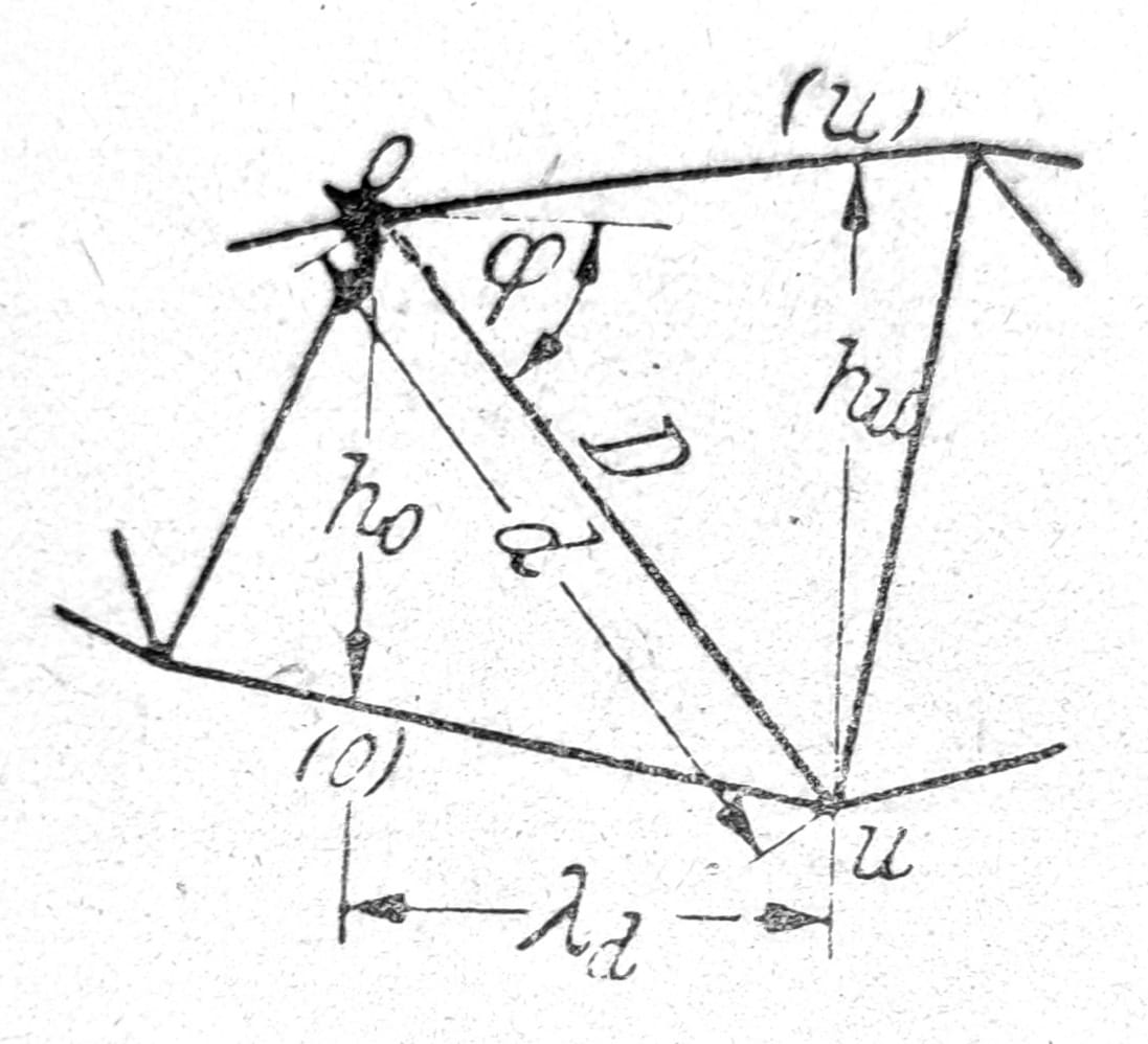
Sl.19
הזזת קווי עומס והשפעה
אם התמיכה עמוסה בעומס נע, כוחות מרוכזים במרחק קבוע זה בזה, אזי הבדיקות צריכות להתבצע ב_מצבי העומס הכי לא נוחים_. לקורה פשוטה על שתי תמיכות, ניתן לקבל את הכוח הרוחבי הגדול ביותר Qmax באמצעות A-מצולע, ואת מומנט הכיפוף הגדול ביותר Mmax באמצעות מצולע השרשרת עבור מערכת הכוחות שמתחתיה נע התמיכה.
בעת קביעת קו ההשפעה עבור כמות סטטית או גיאומטרית אחת, ועבור העומס Pm=1הנעה לאורך החגורה העמוסה של המוביל, עבור כל עמדת עומס m מופעל תחת הכוח, מקו אפס אחד, הערך המחושב ηm של הגודל הנדרש. הקו המחבר את נקודות הקצה של האורדינאטות הללו הוא קו ההשפעה. קווי ההשפעה של מומנט הכיפוף Mi והכוח הרוחבי Qi בנקודה i של הקורה הנתמכת בנקודות a ו-b הינם קווים ישרים ga ו-gb שקטעיהם על האנכיים של התומכים הם aa’ = _xi_ (=M’i עבור _A_1) ו-bb’ = x’i (=M’‘i עבור B=1) (איור20). קו ההשפעה של הכוח A נתון על ידי הישר gb, שהאורינטה שלו על הציר האנכי היא a aa’=1.
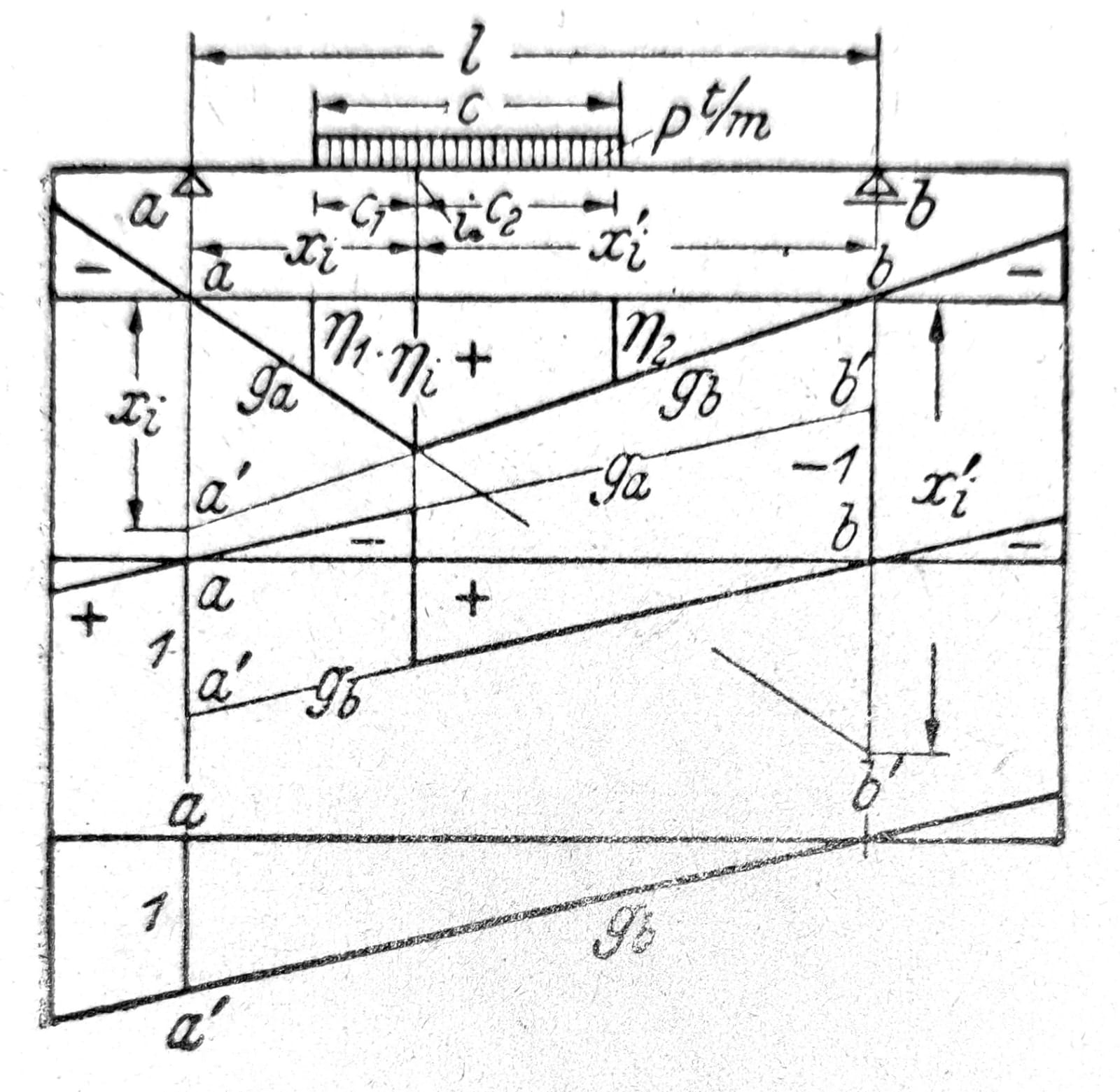
Sl.20
קו ההשפעה עבור כל כמות סטטית של תומך שנקבע סטטית מורכב מ_קווים ישרים_ התואמים ללוחות הקשיחים של השרשרת הקינמטית הכפויה שנוצרה על ידי אי הכללת הכמות המבוקשת. קווים מצטלבים באנכים דרך נקודות מיידיות, או דרך הנקודות שבהן הלוחות תלויים בצירים. השטח התחום על ידי קו האפס, קו ההשפעה ושתי הסמינטות נקרא אזור ההשפעה. ה_מחלק_ (נקודת האפס של קו ההשפעה) מחלק את החלק החיובי והשלילי של משטח ההשפעה.
כמו ηm מייצג את השפעת הכוח הנע Pm=1על הכמות המבוקשת Z, היא Pmηm השפעת הכוח Pm, בעוד שמערכת הכוחות P גורמת להשפעה Z=∑Pη. ערכי הגבול של ההשפעה maxZ ו-minZ יתקבלו כאשר המערכת הנעה של כוחות מרוכזים מחוברים מוגדרת כך שהכוחות הגדולים ביותר מוכפלים באורדינטות הגדולות ביותר. כאשר המיקום הבלתי חיובי ביותר אינו ידוע בוודאות, יש לחשב את ההשפעה מקו ההשפעה זה לצד זה עבור עמדות עומס שונות (תהליך איטרטיבי).
עבור עומס שחולק באופן שווה חלקית p t/m הוא Z = _∫p dx η = pF, כאשר F הוא הגודל המסומן של החלק הרלוונטי של המשטח המשפיע. בעומס חלקי באורך מוגבל c ובצורה ישרה של קו ההשפעה (איור.58) יש למקם את העומס כך ש_η1 = η2 (ג1= cxi/l; ג2= cx’i/l), אז נקבל Z = pc (ηi + η1)/2. בהעברת עומס עקיף, קו ההשפעה נמצא בין האורדינאטות ηn ו-ηn+1 שינויים בקו ישר, איור.21.
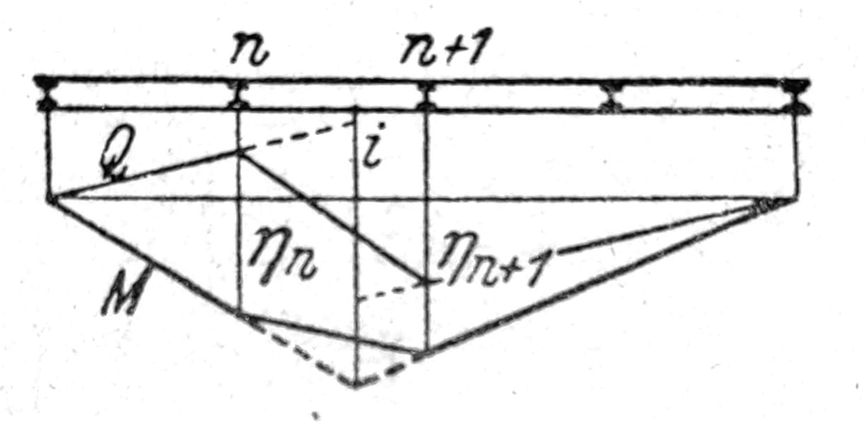
Sl.21