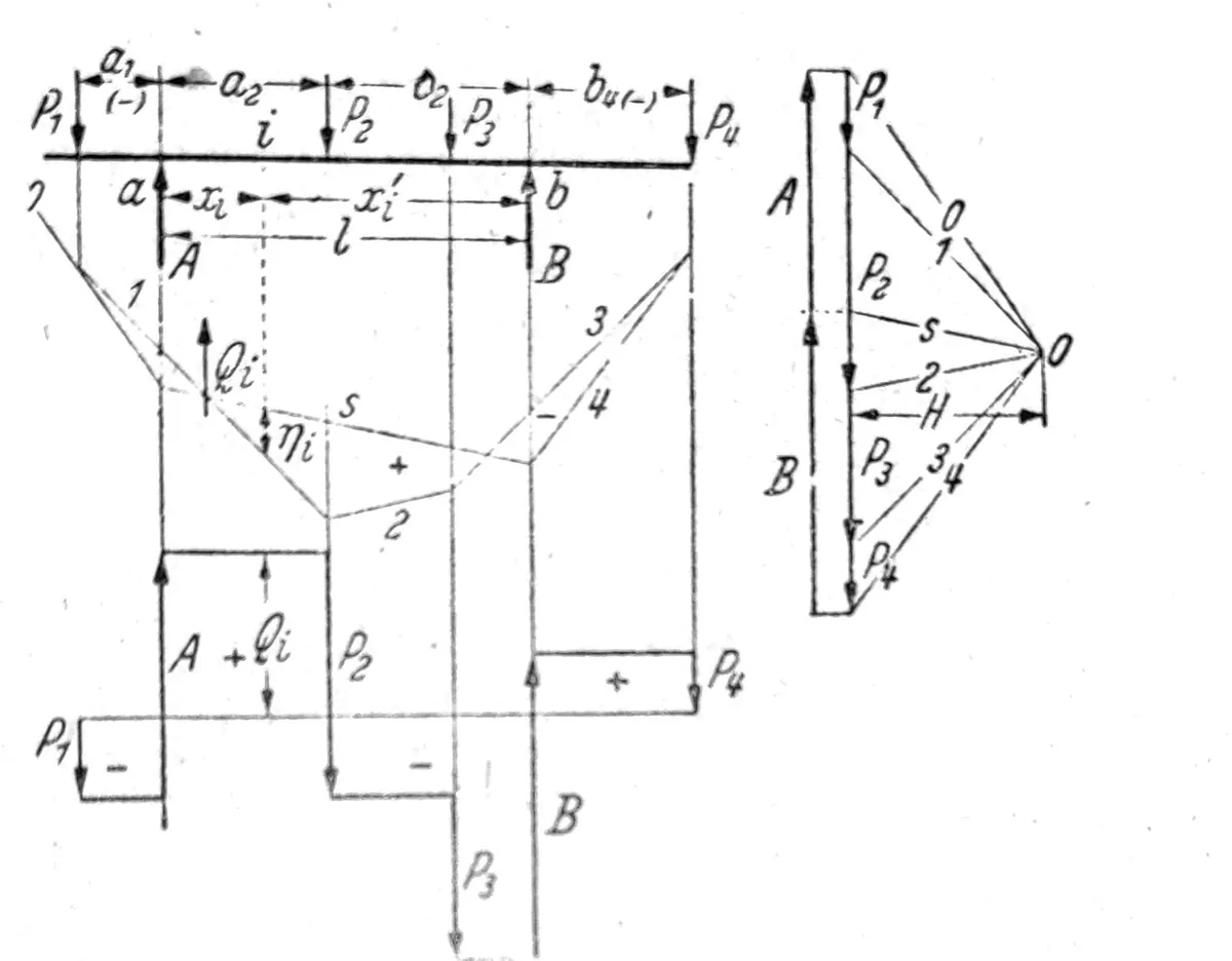
Important Technical and Safety Note: This is an archival educational text, not a static calculation, construction design, or performance manual. Formulas, support models and drawings were transferred from the original content without professional verification or adaptation to today’s regulations. The bearing capacity, stability, loads, materials, joints and foundation for a specific object must be determined by a certified civil engineer based on valid standards, geotechnical data and the actual condition of the structure. The illustrations are educational and do not represent confirmed projects of Savo Kusić.
Static calculations and design of supporting structures are not part of the company’s new public offer. The current production focus consists of wooden windows, wood-aluminium windows and custom-made doors. For a specific window or door project, you can send a request for quotation.
Structure and division of the carrier
Support elements: internal and external stability
The carrier elements are:
Simple rods capable of transmitting only tensile or compressive forces whose line of attack coincides with the axis of the rod. This requires that the rods in the knots are tied with friction-free joints, and that external forces attack the knots. Beams consisting only of simple rods are called trusses.
Sticks resistant to bending - beams - can transmit both forces whose lines of attack coincide with the axis of the rod, as well as forces whose lines of attack are parallel to the axis of the rod or arbitrarily inclined to it. Beams receive normal forces, transverse forces, bending moments and, in the given case, torsion moments. Those in knots can be tied hinged or by means of rigid angles.
Supports and clamps prevent the support from moving towards fixed points in the plane or space. Each support is capable of transmitting a force in a certain direction that passes through the suspended node. If there is only one support in the supported node - support point - it is called a movable bearing of the spatial support. If the node is supported by two supports, it is called a immovable bed of a flat support, or space carrier line bed. The stationary bed of the space support requires three supports.
Each pinch of a bending-resistant rod is able to transmit a pinching moment lying in a certain plane. In most cases, an immovable bearing is connected to the clamp, so that in the case of a flat support there are two supports and one clamp, and in the case of a spatial support there are three supports and three clamps. Movements and rotations of a certain size can occur at the points of support and pinching.
The required number of elements for the stability of the support is obtained from the conditions for internal and external stability. A support is internally stable when the inter-room position of the support nodes is ensured by a sufficient number of rods so that it can be changed only when some or all of the rods change lengths. An internally stable flat support is called a rigid plate. The support is externally or completely stable when the intermediate position of the nodes and their position according to the fixed points of the plane, or space can change only to the extent of the changes in the length of the rods, the movement of the supports or the rotation of the clamping.
Flat supports
The minimum number of rods required for internal stability and the minimum number of rods and supports required for external stability of a truss with s rods, a supports and k nodes is:
s = 2k – 3
s + a = 2k, (3 ≤ a)
The first condition is fulfilled when the support is formed starting from one rod by connecting further nodes with two rods each, whereby the rods to which one node is connected must not lie on the same straight line.
A beam with s1 simple rods, s2 bending-resistant rods, e rigid angles, a1 supports, a2 clamps and k nodes is internal, resp. externally stable when:
s1 + s2 + e ≥ 2k – 3
s1 + s2 + e + a1 + a2 ≥ 2k, (a=a1 + a2 ≥ 3)

Sl. 1
Each rigid angle can be replaced by a simple rod. If in one node i rods are rigidly connected to each other, the number of rigid angles in that node is i-1. When the overhangs of the rods (consoles) are counted as rods, the free ends should be counted as nodes. The bracket in fig. 1 with s1=9, s2=7, e=5 (marked in the picture) and k=12 is intrinsically stable. When we replace the rigid angles 4 and 5 with joints and simple rods, which are marked with broken lines in the picture, then s1=11, s2=7, e=3, while the number of nodes remains unchanged.
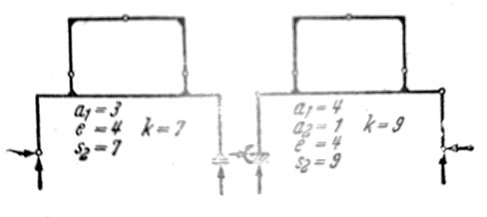
Sl. 2a and 2b
If in one support with the required minimum number of supports, individual rods or rigid corners are replaced by supports or clamps, the support loses its internal stability, fig. 2a, b. For such supports, there are other possibilities of how stability can be tested. If p is the number of rigid plates of the support without internal stability, where it should be noted that a single simple rod or rod resistant to bending meets the conditions of internal stability and can be understood as a rigid plate, and if z is the number of interreactions in the joints, the external stability requires that: a + z ≥ 3p. The number of intermediate reactions in the joint where the plate is attached (fig. 3, 4, 5) is z=2(_i-_1).
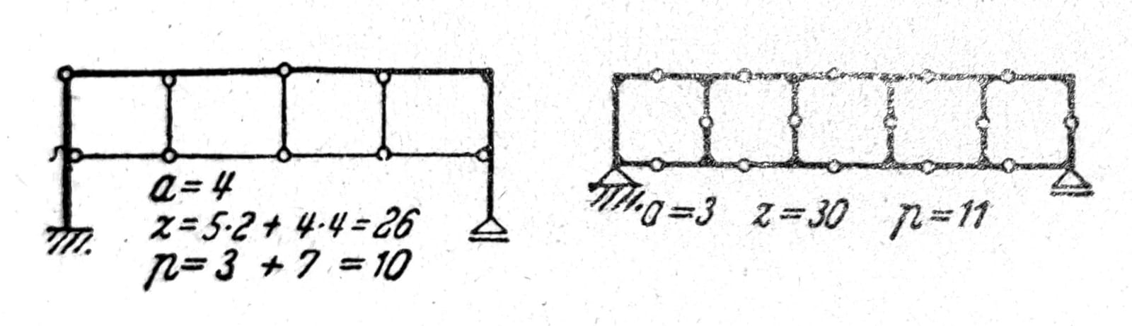
Sl. 3 and 4, respectively

Sl. 5
The frame in fig. 6 is six times statically indeterminate. If the overhangs, which have no influence on the degree of static indeterminacy, are counted as rods, the rigid angles with which they are attached to the system should also be taken into account and the free ends of the overhangs should be counted as nodes (s=7, e=6, a=9, k=8). For these types of supports, the appropriate form of conditions for testing internal and external stability is:
3_s_ ≥ 3k-3; 3s+a ≥ 3k, (a≥3).
At the same time, passes must not be counted as sticks. Often, in such cases, the fastest way to come to a conclusion about the degree of static indeterminacy of the support is by cutting the rods or excluding static quantities until an undoubtedly stable, statically determined support remains. With the three sections indicated in fig. 7 three static quantities (normal force, transverse force, bending moment) are excluded.
If in one n0-times statically indeterminate plane lattice all the rods in the nodes are rigidly connected, the degree of static indeterminacy is
n = n0 + 2s – k.
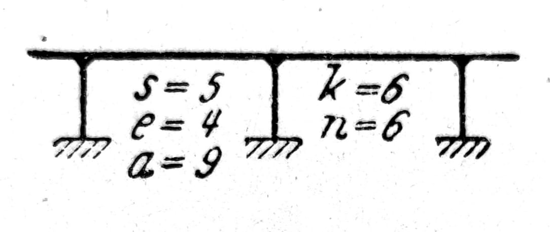
Sl. 6

Sl. 7
Spatial supports
The minimum number of supports for spatial grids is a=6. The following conditions apply to internal and external stability:
s ≥ 3k – 6; s + a ≥ 3k, (a≥6).
The condition for internal stability is met when, starting from one triangular plate, further nodes in the space are tied with three rods each, which must not lie in one plane. In this way, a spatial grid of the first kind is created, the characteristic of which is that it always contains at least one node in which only three rods are tied, and that it retains this feature even when that node with the corresponding rods is removed.
Furthermore, spatial grids can be formed by connecting triangular plates in such a way that two and two plates are connected with six rods, where each node is connected to the adjacent plates with two rods each. The connection of two plates or two internal stable spatial grids can be realized by means of one joint and three rods that do not pass through that joint. Finally, the three triangular plates can be connected with 12 rods with one 4 rod between each plate. For internal, or the external stability of spatial supports where all rods are rigidly tied to bending and twisting, the conditions must be met
6s ≥ 6(k-1); 6s + a ≥ 6k
Therefore, the carrier in fig. 8 is 24 times statically indeterminate, which, as before, can be most easily verified by cutting four horizontal bars and thereby excluding six unknowns in each section (1 normal force, 2 transverse force, 2 bending moment and 1 torsional moment). If we remove f connections by inserting joints in rods or their connections, then the stability conditions are:
6s – f ≥ 6(k-1); 6s – f + a ≥ 6k.

Sl. 8
Load and reactions: statics tasks
In the case of flat supports, the external forces must lie in the plane of the support, in the case of spatial supports, they can have an arbitrary position. In trusses, it is assumed that the load attacks at the nodes.
Active forces cause resistances of external elements, support reactions C in supports and pinching moments E in pinches. The resistances of the internal elements of the supports - shear forces - are: axial forces S in simple rods; in rods resisting bending and twisting normal or longitudinal forces N, bending moments M, twisting moments or torsional moments T and transverse forces Q. The resistances of the elements can also cause changes in temperature and loosening of the supports.
Dimensioning individual elements and determining the stresses that appear in them is the task of Material Resistance. When determining the static values, the applied material is important only to the extent that the permanent load depends on it. Other properties of the material are taken into account only when it comes to the influence of support movement or temperature changes (shrinkage, flow) or when deformations need to be calculated. In general, girders should be tested for various load cases that do not have to occur simultaneously (permanent load, useful load, wind load, snow load). Assuming that the elastic deformations are so small that they can be ignored in relation to the dimensions of the system - and this is usually the case - the principle of superposition applies, according to which individual load cases and other influences may be examined separately and the calculated values for static or geometric quantities added together, with a certain correction of the values through partial safety coefficients for permanent and variable loads (favorable or unfavorable).
Statically determined supports
Unknown and available equations
In a statically determined lattice, the a reaction of supports and s axial forces are unknown, for the determination of which when the lattice has k nodes, 2_k_ equations (∑X=0 and ∑Y=0) in the plane and 3k equations in space are available. In a flat support, the unknowns can be reduced to s1 axial forces of simple members, s2 normal forces of members resisting bending, e bending moments at rigid angles, a1 support reactions and a2 pinching moments. The transverse forces should be determined from the moments at the ends of the rods and the external forces acting between the nodes. In the node from which the i rigidly connected rods depart to the neighboring nodes, it is enough to know the i-1 moment - which corresponds to the number of rigid angles - because the equilibrium condition ∑M=0 is available to determine another unknown moment in each such node. To determine the s1 + s2 + e + a1 + a2 unknowns, 2_k_ equilibrium conditions remain.
Conditions for balance of external forces on flat supports
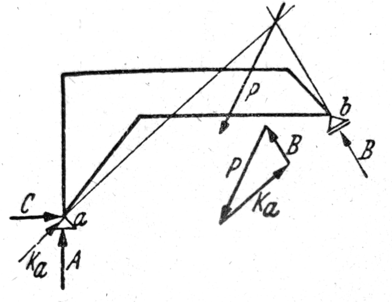
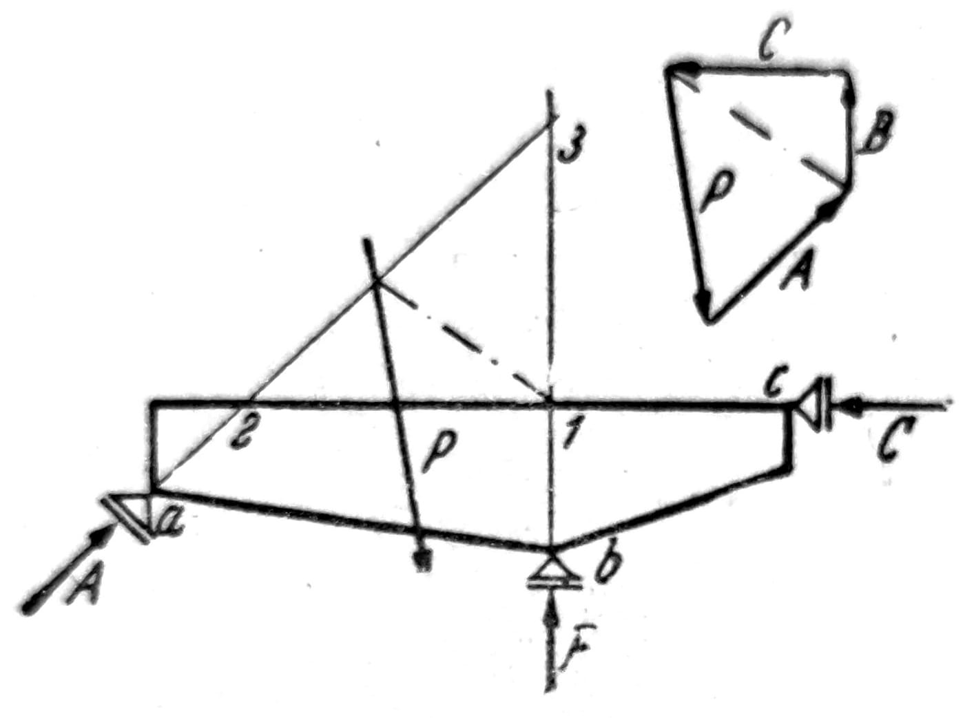
Reactions of plate supports resting on one fixed and one moving bearing (Fig. 9) are obtained graphically using force polygons. The attack line of force B is known and has the direction of support at that point, and the attack line of force Ka must pass through the intersection of forces B and P. Computationally, from the conditions Ma = 0, H = 0 and Mb = 0, the forces B, C and A are gradually determined. The support of the plate on three movable bearings (fig. 10) is correct only when the attack lines of reactions do not intersect at one point. Reactions are determined graphically using force polygons or computationally using moment equations relative to the points where two and two attack lines of forces intersect.
Sl. 9
Sl. 10
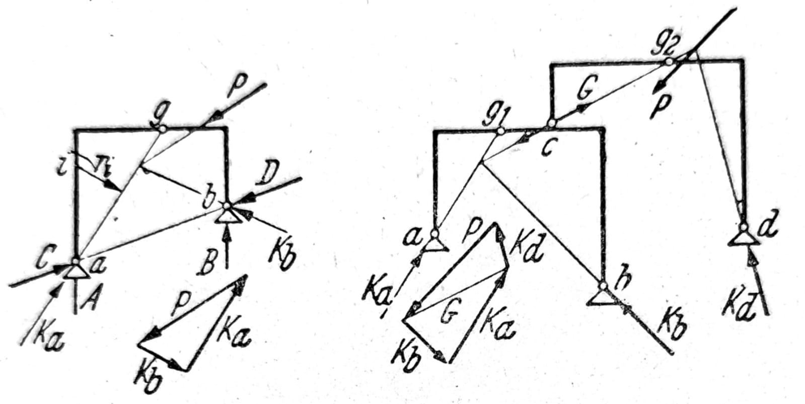
In the case of statically determined supports without internal stability, in addition to the conditions for the balance of external forces as a whole, conditions for the joints are also introduced, which express the requirement that the joints cannot receive bending moments. Therefore, the attack line of reaction Ka of the three-hinged frame in Fig. 11 must pass through the joint g, and the right plate can be in equilibrium only when the three forces acting on it (P, Kb and the joint force = Ka) intersect at one point. In order to obtain equilibrium conditions containing only one unknown each, it is convenient to calculate with the vertical components of reactions A and B and components C and D along the line connecting the support points. From the conditions Mb = 0 and Ma = 0, forces A and B are obtained, and from the conditions for the joint Mg = 0, force C is obtained for the forces attacking the left plate, and force D for the forces on the right plate. In a similar way, the reactions of the frame supports are determined in fig. 12. For the load given here, the fastest way to get the result is graphically. Bracket with joints according to fig. 13. The horizontal components of the external forces acting on the support are received by the stationary bearing, the force F is obtained from ∑H=0. Plate II rests at points g1 and g2 on plates I and III, and plate IV at g3 on III. The vertical forces in the joints G1, G2, G3 and the reaction E are determined from the equilibrium conditions of the plate II or IV, and then the reactions A, B, C and D are determined step by step.
Sl. 11 and 12, respectively

Sl. 13
Determination of internal static quantities
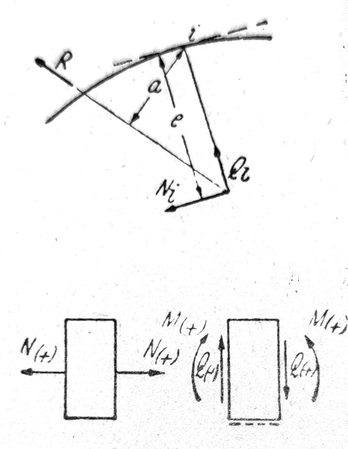
As a rule, axial forces S of simple rods are considered positive when they are tensile forces, and negative when they are compressive forces. In a similar way, the sign of the normal force N in the beam is determined. The normal force Ni at the point i is the component parallel to the tangent to the axis of the beam at the point i of the resultant R of all the forces acting on the beam from one side of the point i. The transverse force Qi is the component normal to the axis of the rod at the point and the same resultant, and the bending moment Mi is the moment of the resultant (fig. 14). Determination of the quantities N, Q and M is performed regularly from individual forces and their components parallel and perpendicular to the axis of the rod without determining the resultant R. The convention of positive directions is shown in fig. 15.
Sl. 14 and 15, respectively
Since the support reactions are determined graphically, the normal forces, bending moments and transverse forces can be determined from the force polygon and the plan in which the forces are given by position. For example, in the left column of the three-hinged frame in fig. 11 the vertical component of the force Ka is the normal force (negative), the horizontal component is the transverse force (negative), and Mi = Kari bending moment, negative when moments causing tension on the inside are considered positive.
The conditions ∑X=0, ∑Y=0 must be met in each node where the rods are hinged. Grids that are formed in the simplest way - by connecting nodes with two rods each - always have at least one node where only two rods meet. By removing such nodes, this feature is maintained. Calculation of axial forces in rods can be carried out by solving two equations with two unknowns.
The graphic solution is obtained by constructing a force plan (Cremana plan) according to fig. 16. The external forces P1 to P6 are in equilibrium. The forces in the rods Si are determined gradually starting from the point 1 and going from node to node in the order they are labeled. Marking of forces is also done in the order in which they are determined. Each node corresponds to a polygon of forces with a continuous arrow direction, from which the signs of the forces in the rods follow. If a section is made through the support and if at the places where the rods are cut the forces acting in those rods are applied as external forces, each part of the lattice is in equilibrium. On this, Culmann's procedure is recorded, by which the force in an arbitrary rod can be determined graphically independent of other forces.

Sl. 16
In the analytical solution of the problem of setting up equations with one unknown each, Ritter’s procedure is of greatest importance. The lattice is cut so that three sticks are affected by the cut. The forces in the section bars are applied to each part of the truss as tension forces, from the node to the section. Equilibrium conditions apply to each part of the lattice. The intersection of two and two intersecting rods is the moment point when determining the force in the third rod (Ritter's point). If ri is the distance of the force Si from the moment point i, and Mi is the moment of the active forces and reactions of the supports in relation to the point i, then the force in the rod is given by the expression
Si = ± Mi/ri

Sl. 17

Sl. 18
According to fig. 17 and 18 forces in cross-sectional rods are:
On = -Mn/rn; Un-1 = Mn-1/rn-1;
Dn = Md/rd; Ln = Mv/rv.
When the graphic construction does not provide sufficient accuracy, the positions of the moment points d and v and the distances rd and rv must be calculated. For the calculation of forces D and L, the following expressions are more suitable, in which only the characteristic points of the grid appear as moment points (fig. 19, 18):
D = (Mu/hu – M(o)/ho) * (d/λd), (35)
Ln = ± Ql ± (Mn tgβn + M’n tgγn)/hn.
For gratings with parallel belts, the forces D and L can be obtained directly from the transverse force:
D = Q/sin__φ_; L=__±Q_
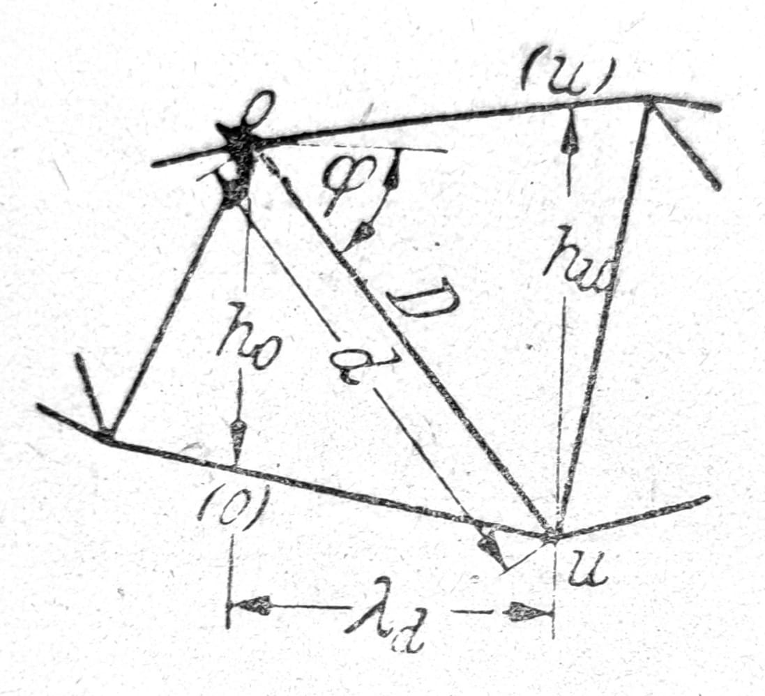
Sl. 19
Live load and influence lines
If the support is loaded with a moving load, concentrated forces at a constant distance between each other, then the tests should be carried out at the most unfavorable load positions. For a simple beam on two supports, the largest transverse force Qmax can be obtained using the A-polygon, and the largest bending moment Mmax using the chain polygon for the system of forces under which the support moves.
When determining the influence line for one static or geometric quantity, and for the load Pm=1 moving on the loaded belt of the carrier, for each load position m, the calculated value ηm of the required quantity is applied under the force, from one zero line. The line joining the endpoints of these ordinates is the line of influence. The influencing lines for the bending moment Mi and the transverse force Qi at the point i of the beam supported at the points a and b are straight lines ga and gb whose sections on the vertical supports are aa’ = xi (=M’i for A=1) and bb’ = x’i (=M’‘i for B=1) (fig. 20). The line of influence for the force A is given by the line gb, whose ordinate on the vertical axis is a aa’=1.
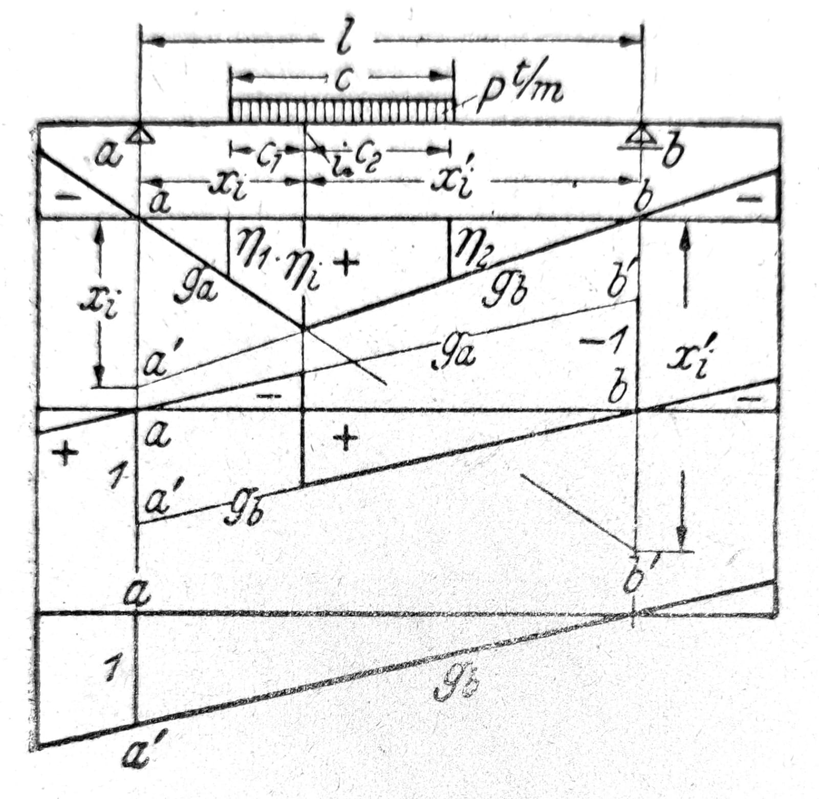
Sl. 20
The influence line for each static quantity of a statically determined support consists of straight lines corresponding to the rigid plates of the forced kinematic chain created by the exclusion of the requested quantity. Lines intersect at verticals through instant points, or through the points where the plates are hinged. The area bounded by the zero line, the influence line and two ordinates is called the influence area. The divider (zero point of the influence line) divides the positive and negative parts of the influence surface.
Since ηm represents the influence of the moving force Pm=1 on the required quantity Z, it is Pmηm the influence of the force Pm, while the system of forces P causes the influence of Z=∑Pη. The limit values of the influence maxZ and minZ will be obtained when the moving system of connected concentrated forces is set so that the largest forces are multiplied by the largest ordinates. When the most unfavorable position is not known with certainty, the influence from the influence line must be calculated side by side for different load positions (iterative process).
For partially equally distributed load p t/m is Z = _∫_p dx η = pF, where F is the marked size of the relevant part of the influence surface. In the case of a partial load of limited length c and a rectilinear shape of the influence line (fig. 58), the load should be set so that η1 = η2 (c1 = cxi/l; c2 = cx’i/l), thus obtaining Z = pc (ηi + η1)/2. During indirect load transfer, the influence line between the ordinates ηn and ηn+1 changes in a straight line, fig. 21.
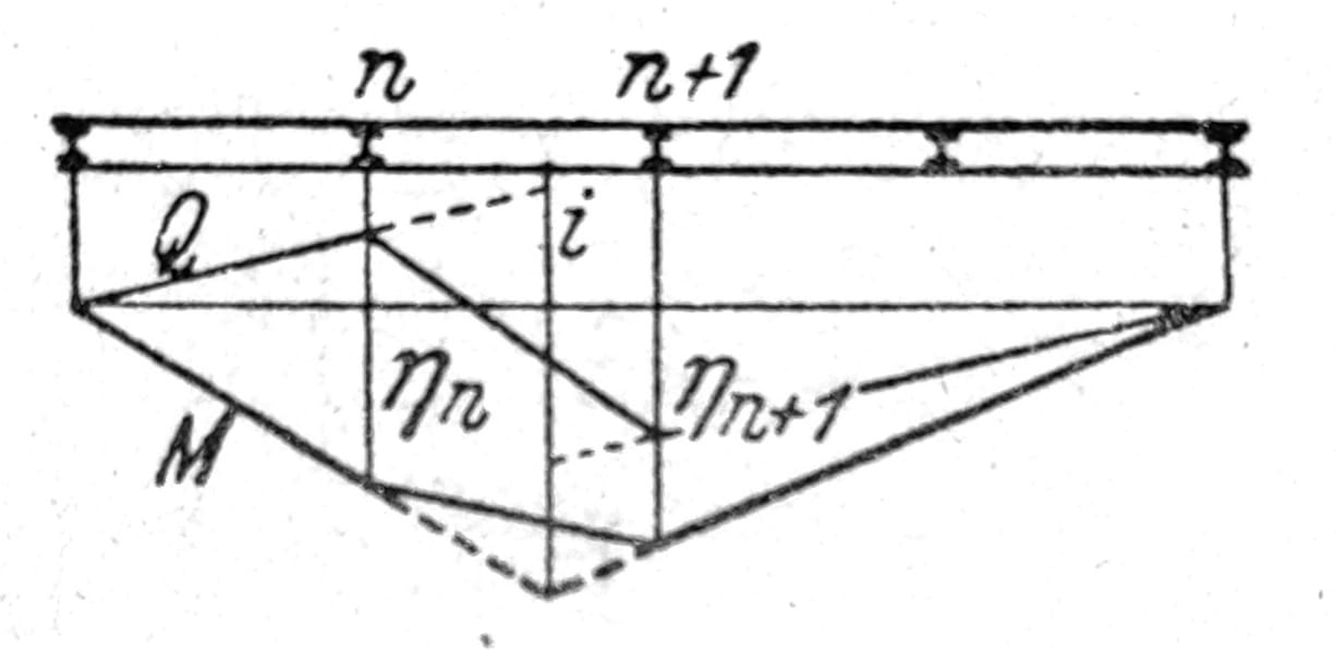
Sl. 21