Archival expert content: the article preserves historical procedures, formulas, tables and drawings in the field of static structures, but is not a project, static calculation, proof of load capacity, assembly plan or assessment of an existing building. Supports, spans, loads, combinations of actions, geometry, materials, connections, stability, fatigue, seismicity and construction phases must be determined for a specific object according to valid standards. Load-bearing structures are designed and checked by responsible authorized engineers.
Today, Savo Kusić is focused on wooden windows, wooden-aluminum windows, custom windows, doors and requests for quotation. This article remains as a historical archive and does not represent an offer of design, calculation or execution of building structures.
Formulas and Marks: mathematical expressions in the text have been digitally transferred from a scanned source and may contain typographical or OCR errors. They must not be entered into a calculation without comparison with an authoritative source, checking units, signs, assumptions and boundary conditions.
A simple beam
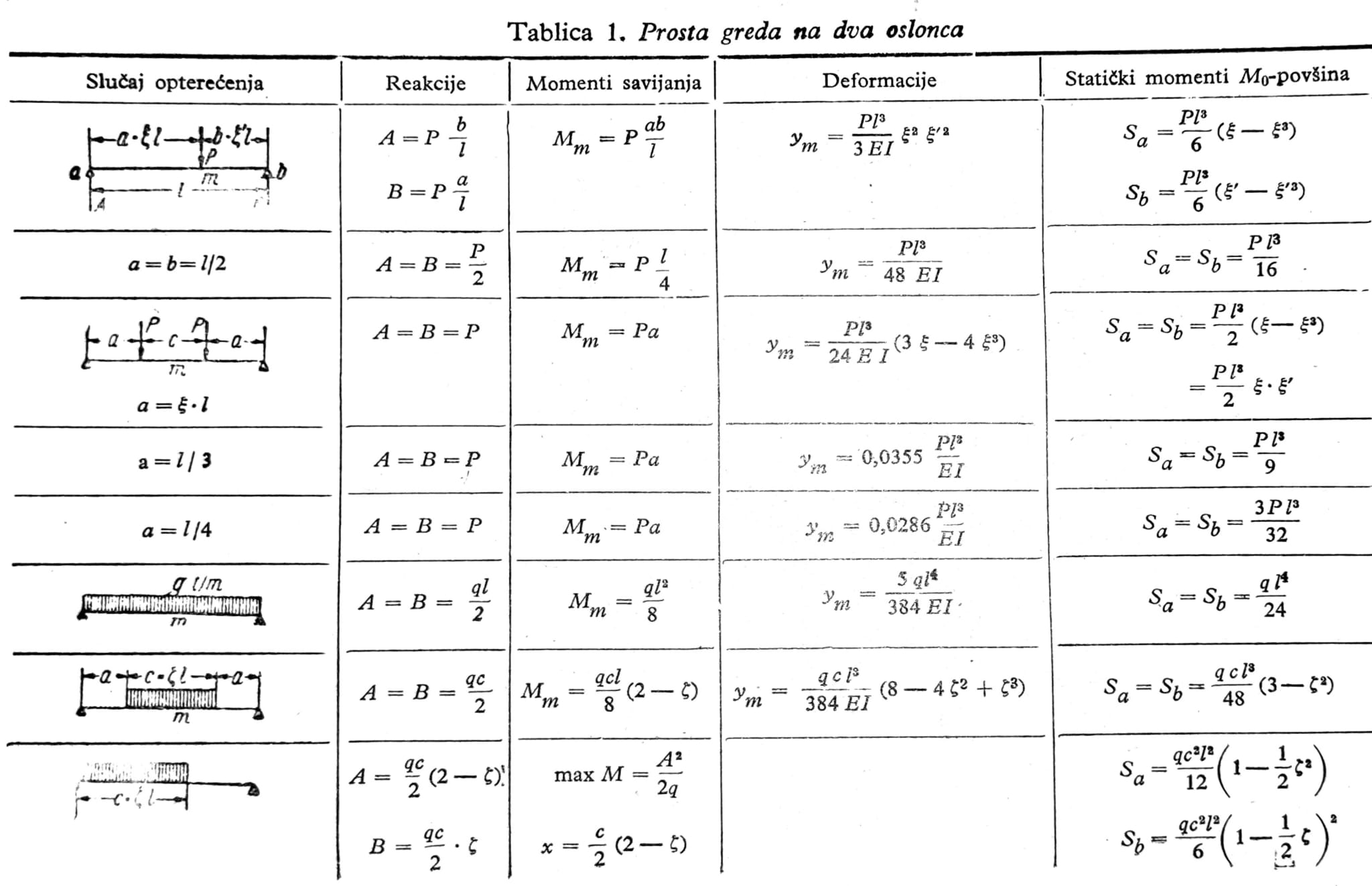
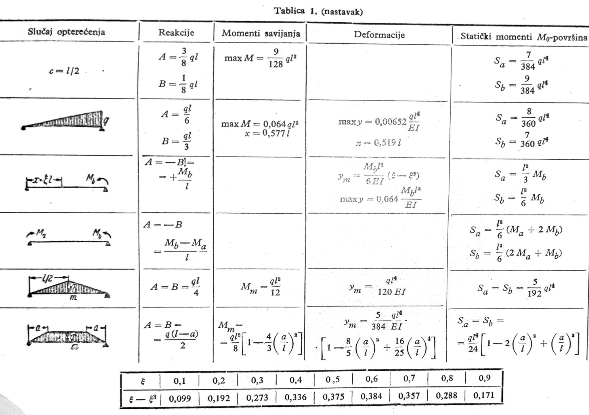
Support reactions, bending moments, deformations and static moments of the M0-surface for some frequently occurring load cases are given in table 1.
Constant load with concentrated forces
In the case of a symmetrical load (Fig. 1), the calculation is easiest to carry out by means of two addition columns in the form of a table. Based on the relationship between load, transverse force and moment
_Qn = Qn+1 + Pn and Mn+1/_λ _= Mn/_λ + Qn+1
first, the transverse force in the field n is determined starting from the transverse force in the middle of the beam and then the bending moments in individual points starting from the value Mi/λ.

Fig. 1 with auxiliary tables.
When the load is asymmetric and the force distances are equal, the following tables are suitable for calculation (fig. 2). Any asymmetric load can be according to fig. Replace 3 with one antimetric load, which is often very useful in the calculation. Instead of the forces Pi and P’i in the case of a symmetrical load, the forces (Pi+P’i)/2 appear in the points i and i’, and in the case of the antimetric load, the force (Pi-P’i)/2 appears in the point i and force -(Pi-P’i)/2 at point i’. When the support reactions are determined under antimetric loading, the transverse forces and bending moments can also be determined in the table.
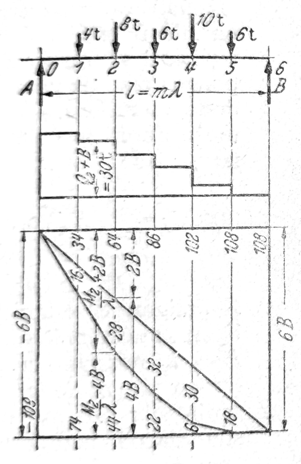
Fig. 2.

Fig. 3.
Moving load
The bending moment at the location i is obtained graphically using the force polygon and the chain polygon for the given load. A chain polygon can be drawn as shown in fig. 4. To determine the most unfavorable load position for the moment at location i, the support is moved under load (fig. 5) until the value max η__i is determined, from which max_Mi_ = H * max_η__i_ is obtained. The largest transverse force at point i is obtained when the load is moved so that the first force reaches point i. It can be obtained from the polygon of forces in fig. 6: max_Oi_ = 1_/l_ * ∑Pibi. A-polygon is a chain polygon with pole distance H = l, drawn for a moving system of concentrated forces when the first force is located over the support b.
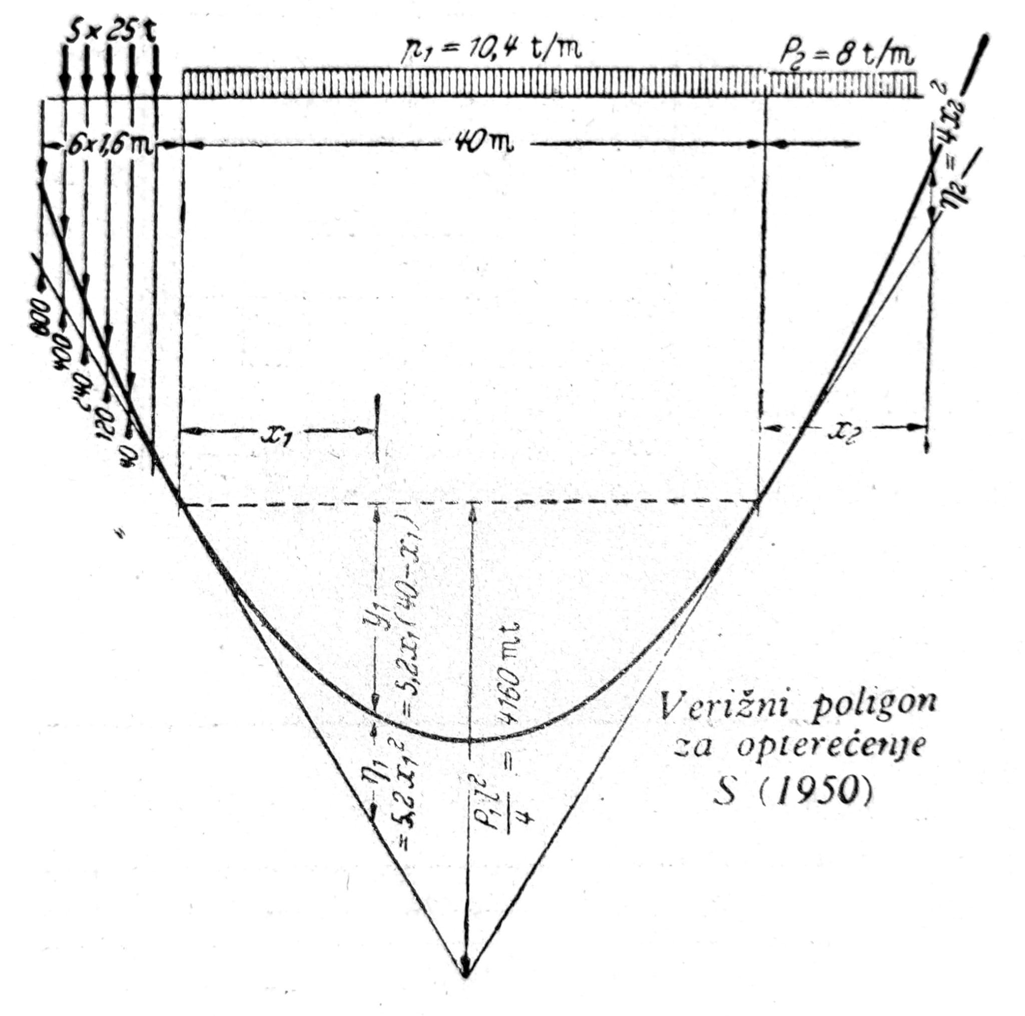
Fig. 4.

Fig. 5.

Fig. 6.
Moving loads: the selection of the relevant position and combination of moving loads depends on the purpose of the structure, the model of action, dynamic influences and valid regulations. The historical graphic procedure is not enough proof of the most unfavorable state of the modern construction.
Bracket with joints
Constant load
First, the reactions of the supports and forces in the joints are determined from the equilibrium conditions and the conditions for the joints. Then, bending moments and transverse forces for individual support plates can be determined as for simple beams, or beam with overhangs. Sl. 7 shows the result for loading three plates with concentrated forces. The line of transverse forces passes over the joints as a constant, and the moment line without breaks, if there is no concentrated force in the joint.

Fig. 7.
For an equally distributed load on the entire support, some large differences between the moments over the supports and the maximum moments in the fields are obtained, according to the span ratios and the position of the joints, fig. 8. If for a support with joints with more than two openings (fig. 9) and with equal spans l of middle fields, the range of end fields l1=0,8535_l_ and the position of the joints c=0,1465_l_ is chosen, then to an equally distributed load, it is obtained that the limit values of the moments over the supports and in the fields are mutually equal, M=0,0625_gl_2. If the end fields also have a range of l, then for them max_M_=0,0957_gl_2.
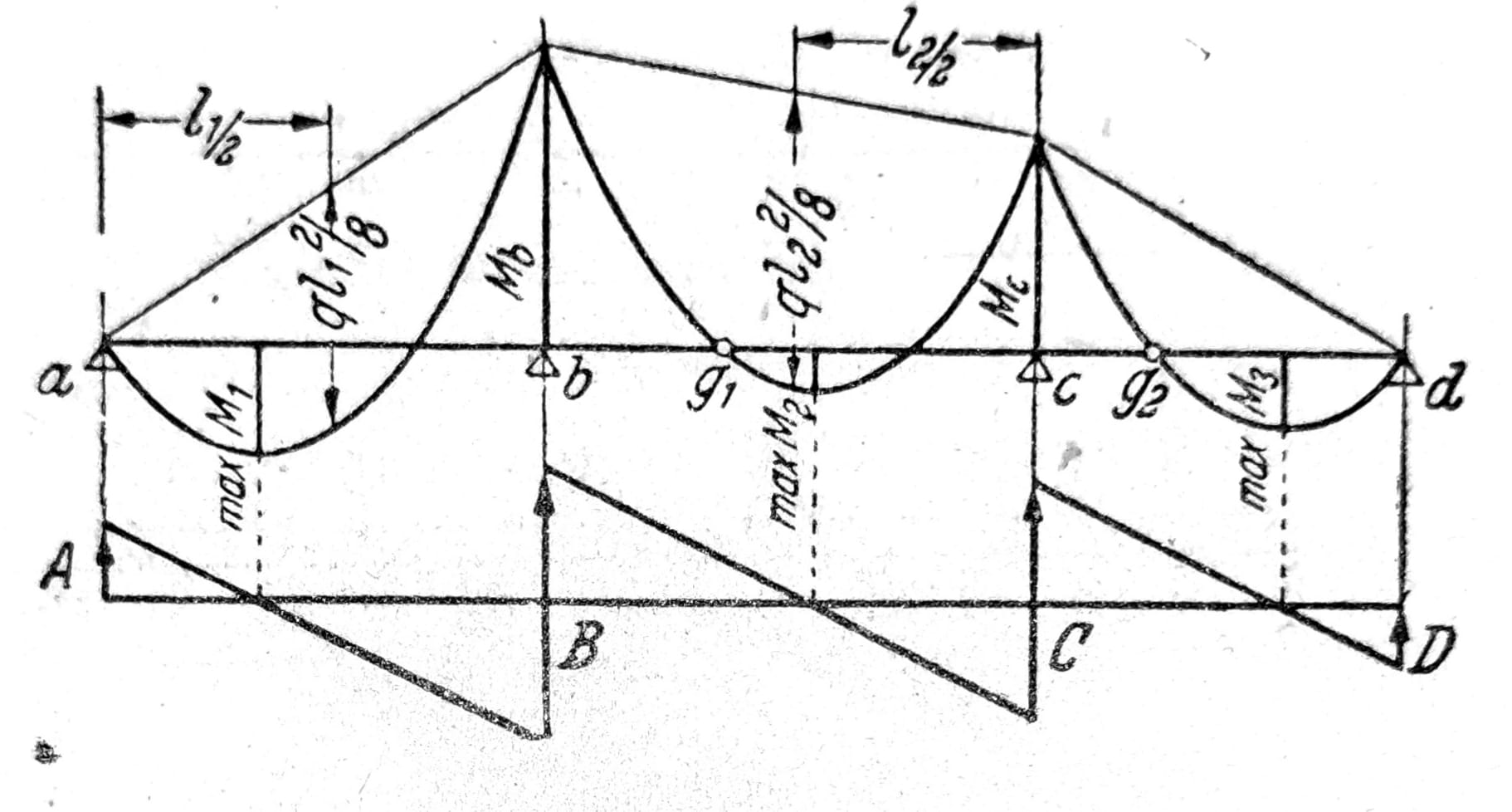
Fig. 8.
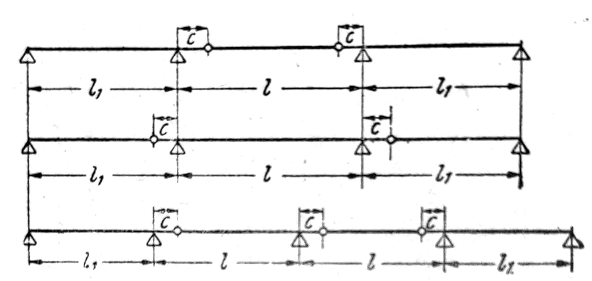
Fig. 9.
Influence lines
According to fig. 10 influence lines for Mi and Qi between points a and b are the same as influence lines of simple beam. The further course of the influential line is determined by the position of supports and joints that represent the main poles and intermediate poles of the kinematic chain created by removing the static quantity at point i. In a similar way, the influence lines for Mr and Qr are determined starting from the beam supported at points g1 and c. The load of the beam with an overhang at the section ag1 has no effect on the moments and transverse forces at the point r. Influence lines for moments and transverse forces at the overhang points (k and v) are most easily obtained when the ordinates for the position of the load in the joint are determined.
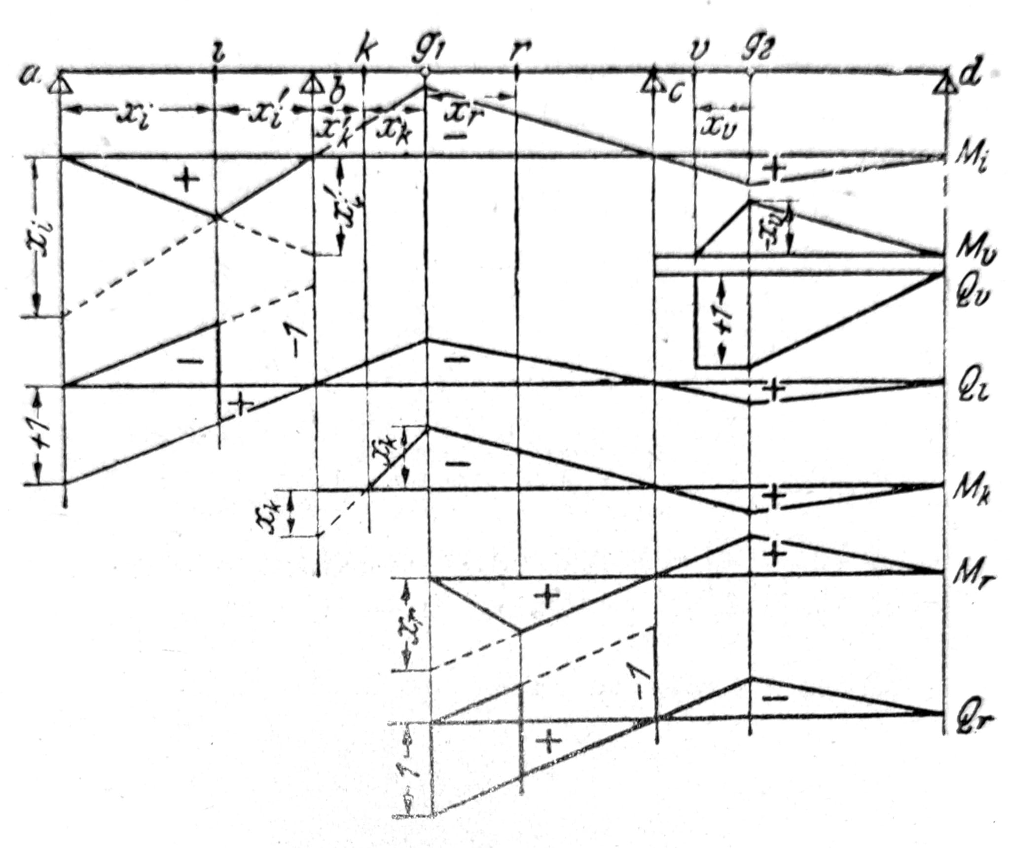
Fig. 10.
Model of supports and joints: actual stiffness of joints, settlement of supports, clearances, friction, imperfections and sequence of assembly can change the distribution of forces compared to the idealized model. Assumptions must be reconciled with construction details and verified for all relevant phases.
Bow on three joints
With arbitrary loading of the arch on three joints, the reactions of the supports can be determined graphically. Resultant R1 of active forces which according to fig. 11 acting on the left plate must be in balance with reaction Kb1, whose attack line must pass through joint g, and reaction Ka1. In the same way, Ka2 and Kb2 are found, due to R2. With the simultaneous action of R1 and R2, the final reaction forces Ka and Kb and joint pressure G are obtained by parallel displacement and stacking.
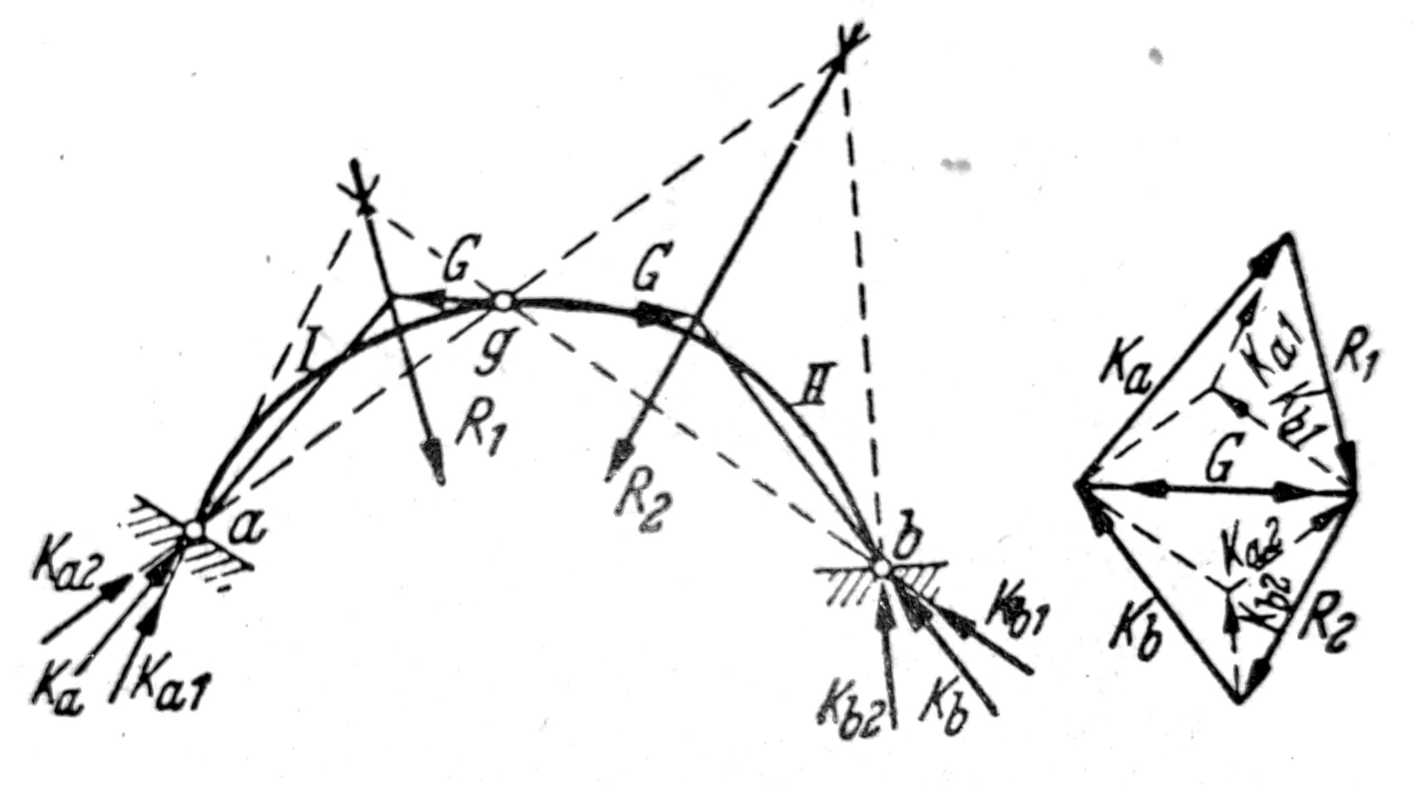
Fig. 11.
With the analytical solution, it is convenient to carry out the calculation especially for horizontal and especially for vertical loads.
Horizontal load
The horizontal load in fig. 12 causes reactions
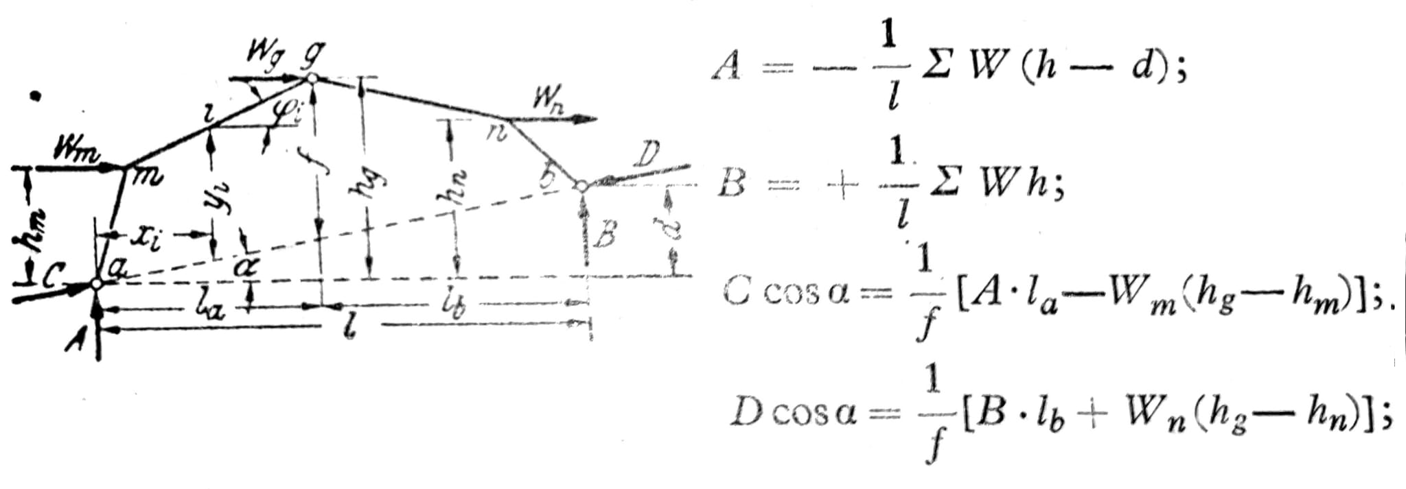
Fig. 12.
where C and D are the reaction components in the direction connecting the points a and b. ∑H = C*cos_a_ – D_cos_a + W = 0 is used for control. The shear forces in place are:
Ni = -Asin__φ__i – Ccos(φ__i-a) – Wmcos__φ__i_,_
Qi = +Acos__φ__i – Csin(φ__i-a) – Wmsin__φ__i,
Mi = A__x__i _– Ccosa*_y__i – Wm(hi-hm).
Vertical load
The vertical load of the arch on the three joints in fig. 13 causes the reactions A0 and B0, which are equal to the reactions of the simple beam of span l, and the horizontal thrust C=cosa = Dcosa = H = Mg0/f (1), where Mg0 is the moment on the simple beam in section g. With vertical components C and D the final vertical components of the reactions are A = A0 + H_tg_a; B = B0 – H_tg_a. If the axis of the arch is a square parabola, yi = f xi x’i/la lb, then for equally distributed full load g t/m (fig. 14) Mi=0, Qi=0.
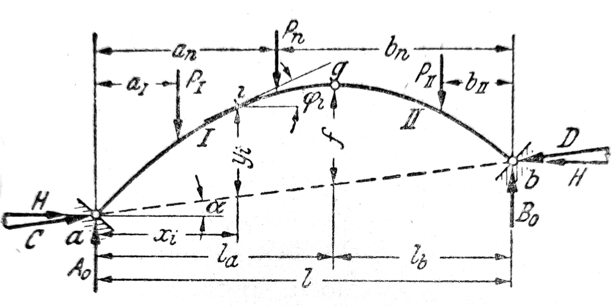
Fig. 13.
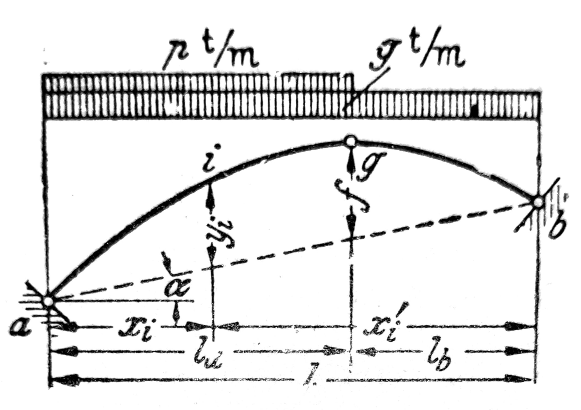
Fig. 14.
Influence lines
The influence lines for reactions A0 and B0 are the same as the influence lines of a simple beam. The influence line for the horizontal thrust H is obtained according to the equation (1) from the influence line for the moment Mg0 of the simple beam, fig. 15. The influence line for the bending moment Mi consists of the influence lines with Mi0 and H, where the latter is multiplied by -yi. These two influential lines are superimposed on the straight line ab’ as a zero line, from which sections aa’ = xi i bb’ = -lb yi/f are applied. The difference shown by stroke ai’g’b represents the final influence line for Mi. The divider or zero point of the influence line corresponding to the main pole of the plate ig is obtained by the intersection of the lines ai and bg. It can also be used for the construction of the influence line, where a simple beam of span a – n is introduced. In the case of an arch whose axis is a square parabola, the equally distributed load does not cause bending moments, so the total area of the influence line must be equal to zero.
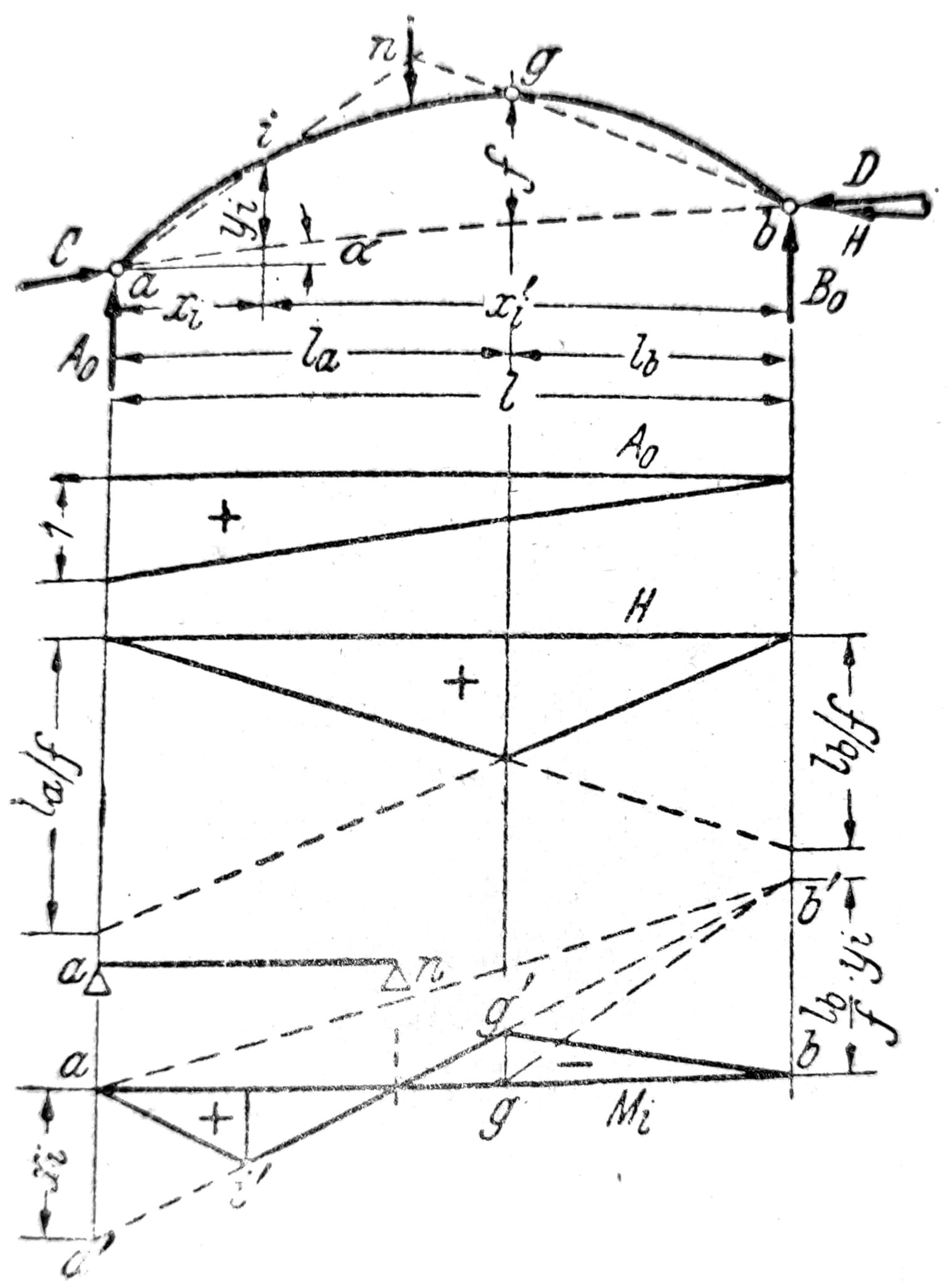
Fig. 15.
In fig. 16 influence lines for Qi and Ni were obtained by corresponding superposition of influence lines for Qi0 and H. In relation to ab’ as a zero line, both influence lines are in this case the influence lines of a simple beam. The sections nQ and nN of the line bg and the line drawn through a parallel can be used here for the construction or control of influential lines, respectively. normal to the tangent that overlaps the angle φ__i with the horizontal. In the case of a parabolic arch with three joints, the total area of the line of influence for the transverse force must be equal to zero.

Fig. 16.
Arches and horizontal thrust: the position of the joints, the geometry of the axis, the stiffness of the foundation and the acceptance of horizontal reactions are crucial for the behavior of the system. Changing the support, tension, hanger or mounting phase can change the flow of forces; a historically idealized drawing is not sufficient for execution or rehabilitation.
Arch stiffened with a beam and hanging bracket
Vertical load
Vertical reactions during vertical loading of rigid plates of statically determined arch supports stiffened with a beam, hanging supports and arches on three joints and tension in Fig. 17 a to f are obtained from the equations A0 = 1/l * ∑Pnbn and B0 = 1/l * ∑Pnan when for the systems a and d put A0 = A+K’‘l, B0 = B+K’’r and for other systems A = A0, B=B0. The reactions A and B for the systems a and d are then determined from:
A = A0 – K’’l = A0 – H(tgal-tg__δ)
B = B0 – K’’r = B0 – H(tgar+tg__δ)
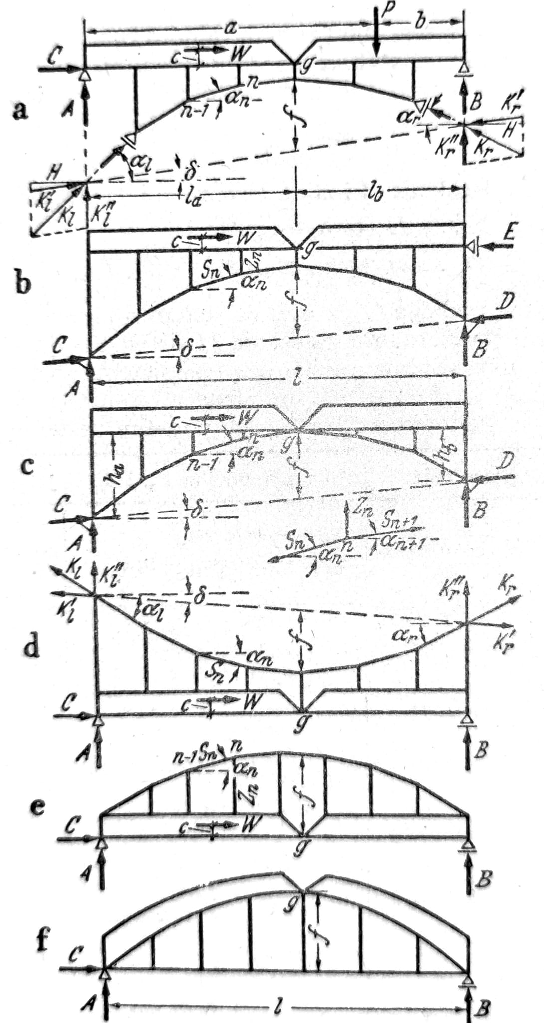
Fig. 17.
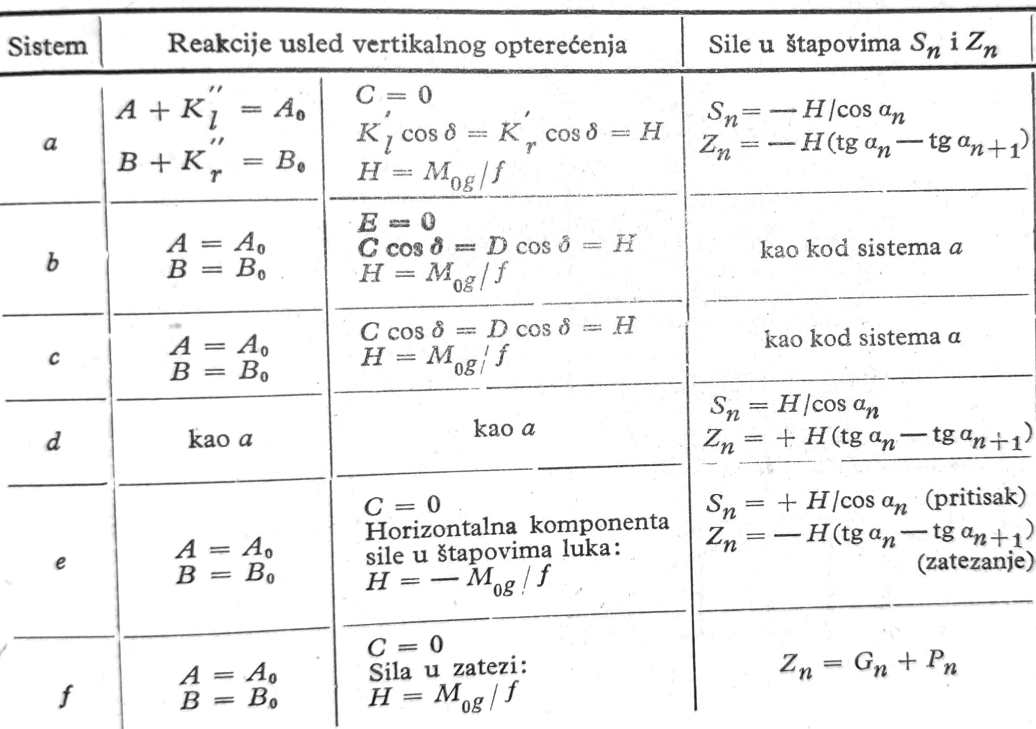
For the systems a, d, e and f the horizontal reaction is C=0, and for the system b it is E=0. Horizontal thrust, or the horizontal tension H of the system a to d, the horizontal component of the force in the arch of the system e and the force in tension of the system f are determined based on the equation (1). The following table contains an overview of the reactions of supports and forces in rods Sn and Zn for individual systems.
Horizontal load
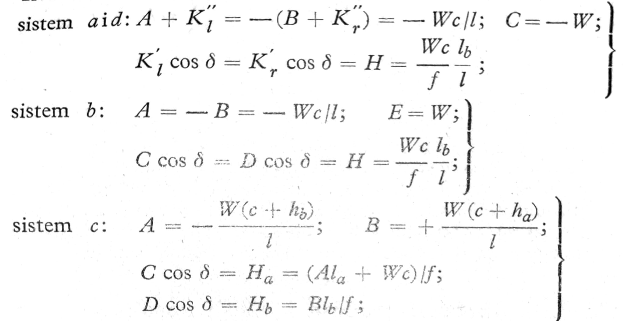
If a horizontal force W acts on the plates at a distance c from the joint g (fig. 17 a to e) the reactions of the supports that it causes are:

Influence lines
The influence lines for the shear forces are obtained based on the similarity in the behavior of these systems and a simple three-hinged arch. For a stick arch with a stiffening beam under the arch (Langer beam) in fig. 18 shows the influence lines for U2, D4 and L4. The force in the rod U2 is obtained from the moment for the point 2 of the upper belt: U2 = M2/h. From the condition ∑V=0 we get D4 = Q40/sin__φ – Mg0/f tga4/sin__φ. Also from the condition ∑V=0 it follows (load on the lower belt) L4 = -Q50 + Mg0/f * tga4.
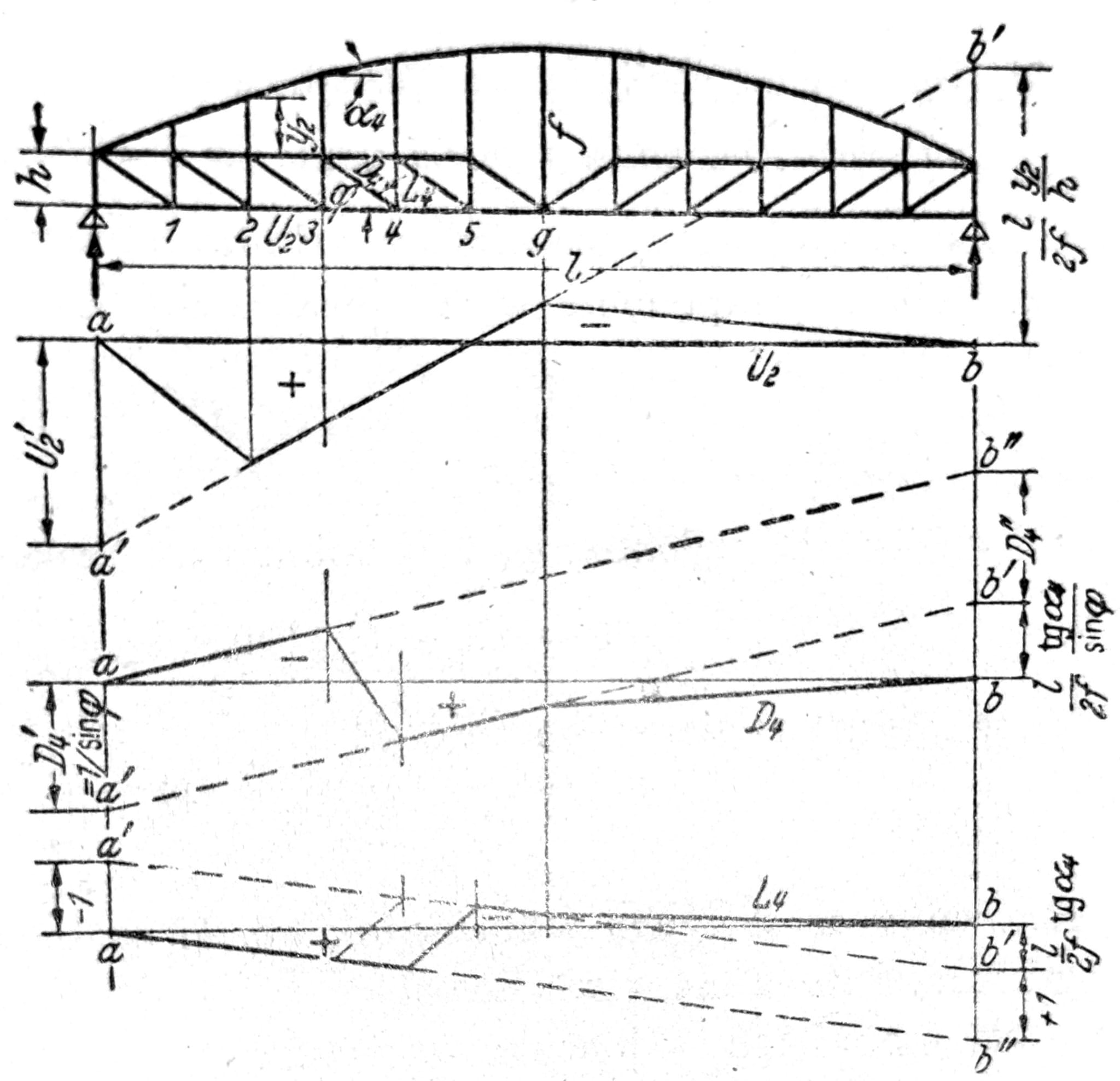
Fig. 18.
If the nodes of a three-jointed arch with a solid beam for stiffening (fig. 19) lie on a square parabola and if the joint lies in the axis of the beam, then with an equally distributed load g t/m the bending moments M=0 are at the places of the hangers, and M=g__λ__2/8 in the middle of the field between the hangers.
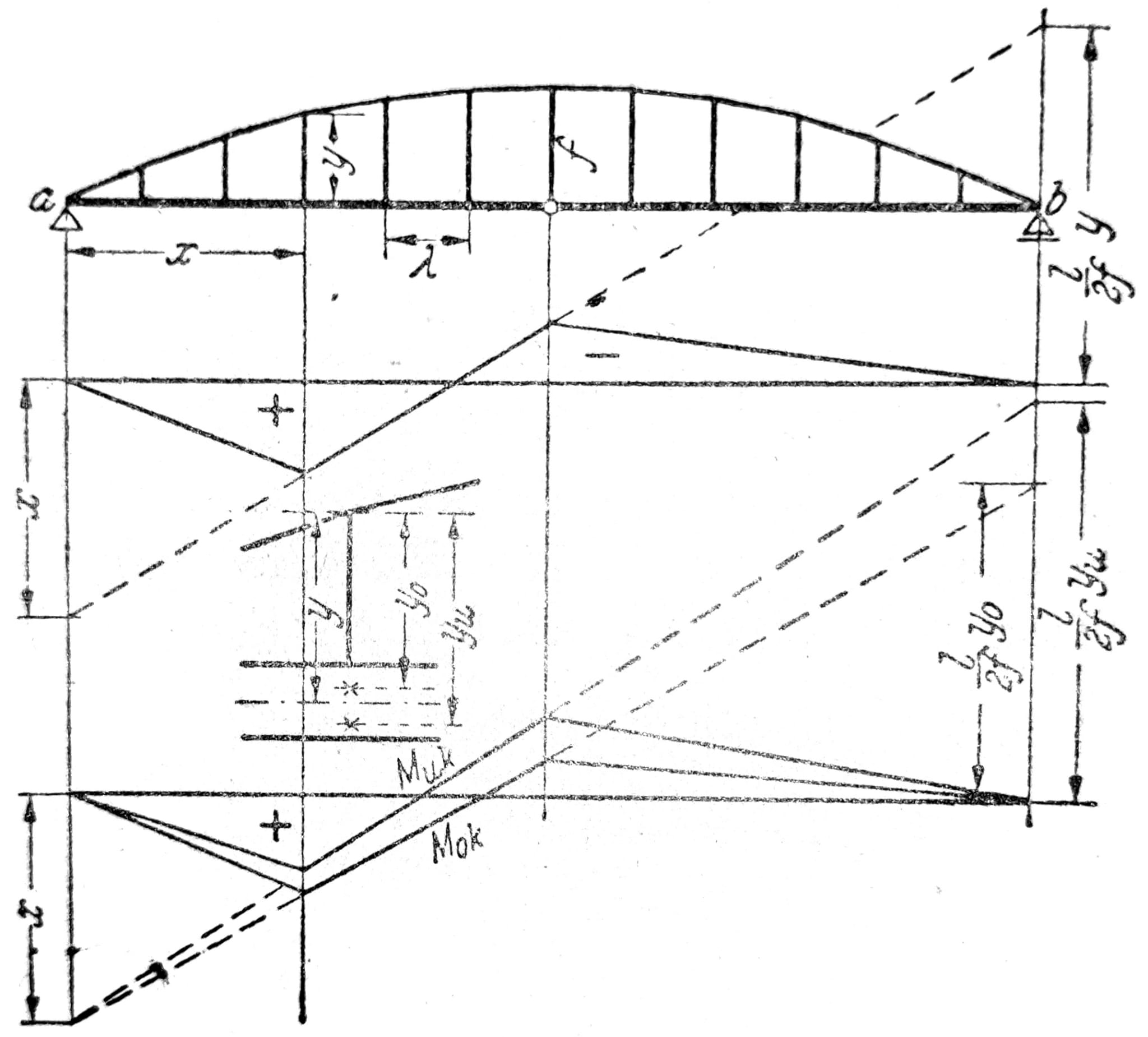
Fig. 19.
Hangers, tensioners and stiffeners: these elements and their connections can be sensitive to imperfections, secondary stresses, fatigue, corrosion, loss of prestress and assembly conditions. Their replacement, tightening or removal is not carried out without a temporary and final state project.
Frame supports
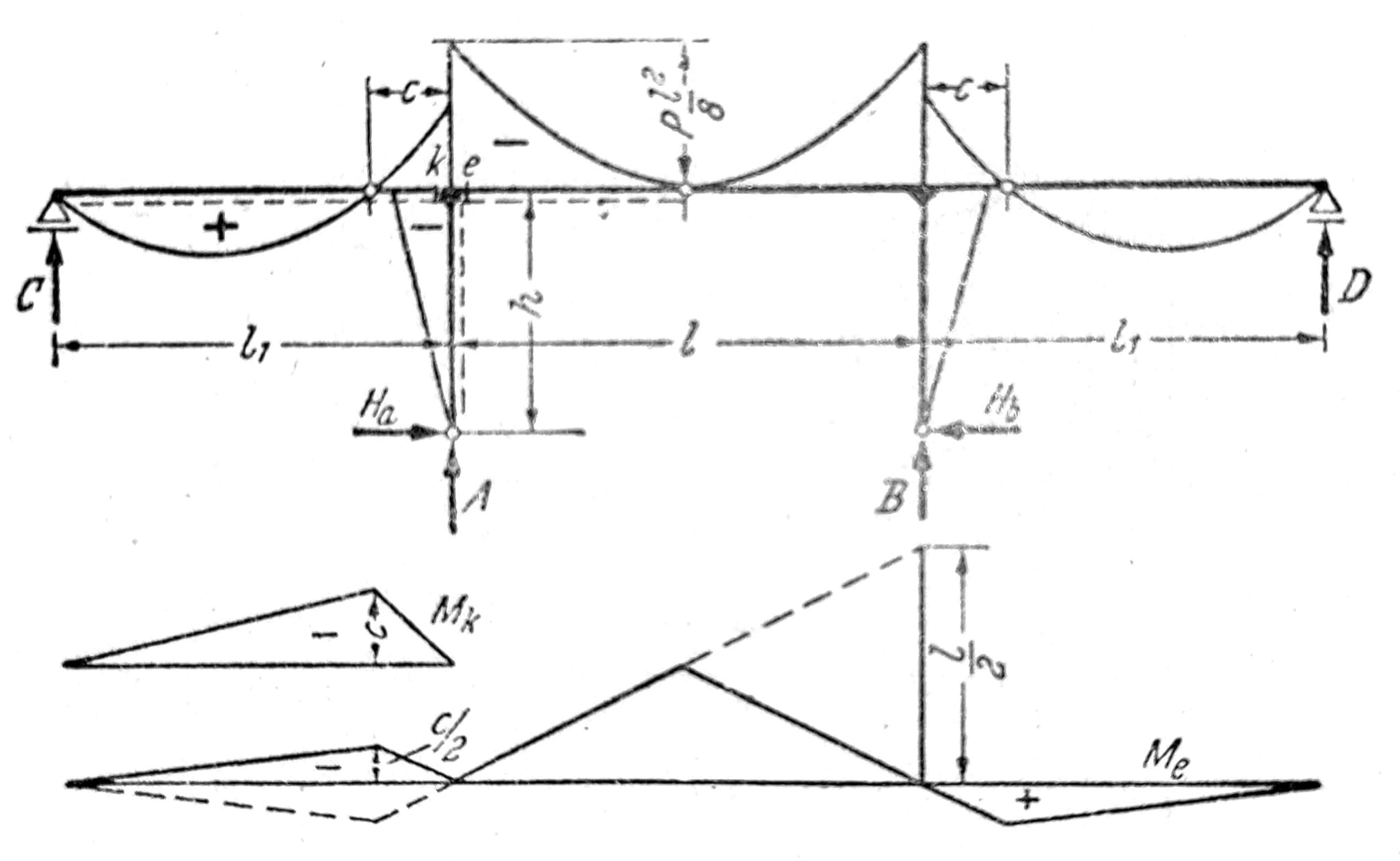
Fig. 20.
Sl. 20 shows the moment diagram of a three-hinged frame with overhangs and suspended girders due to equally distributed full load. The influence line for the moment Me is obtained based on the expression Me=-Hh + Mk, by superposition of the influence line for the horizontal thrust H (with multiplier -h) and for the bending moment Mk on the overhang.
In the case of non-symmetric loading of symmetric supports, the calculation can often be simplified by dividing the load into symmetric and anti-symmetric loading, fig. 21. This is especially true for the frame supports in fig. 22 and 23, which show the moment diagrams due to the concentrated force at an arbitrary place of the upper support. The horizontal load at the height of the joist can be understood as antimetric. Since the horizontal load of the sub-strut can be considered as a virtual load for the calculation of the horizontal displacements of the sub-strut, it can be immediately concluded from the moment surfaces to which side the sub-strut moves during the vertical load. These displacements are obtained by combining antimetric equilibrium states. Therefore, for the cases in fig. 22 and 23 the underline moves to the right.

Fig. 21.
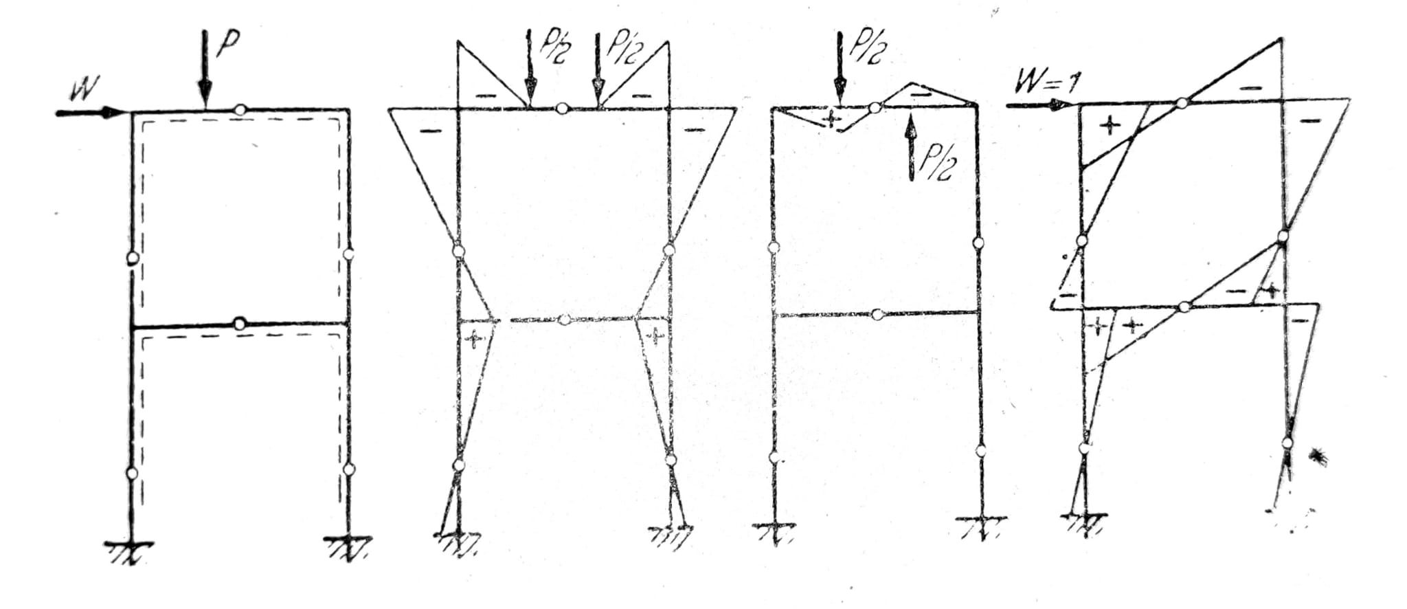
Fig. 22.
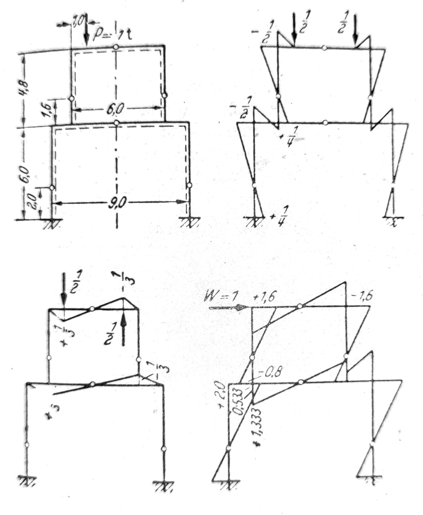
Fig. 23.
Frames and displacements: the conclusion of the direction of displacement from an idealized diagram does not replace the checking of deformations, second-order effects, stability, stiffness of joints, foundations and non-bearing elements. The load-bearing and serviceability limit states are checked on the complete model.
Spatial grids
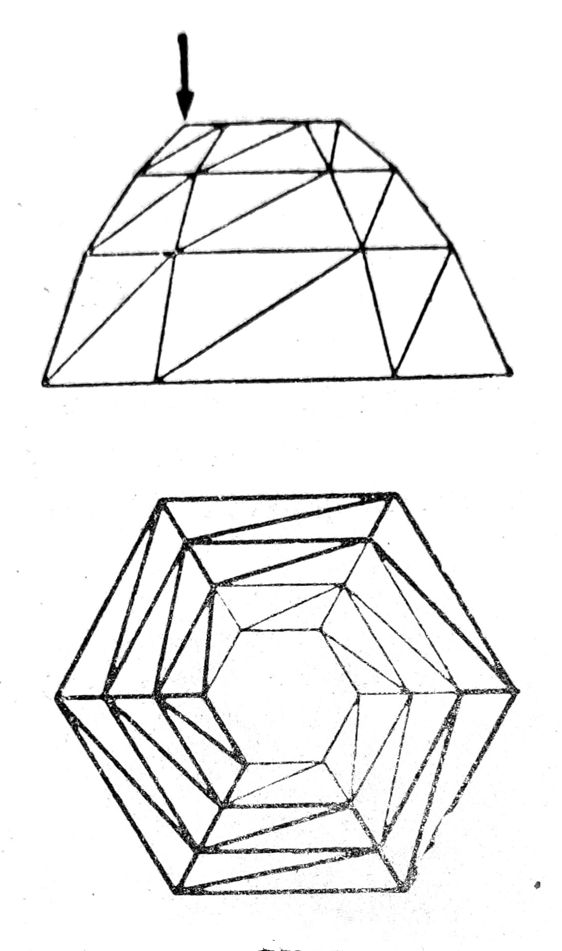
Fig. 24.
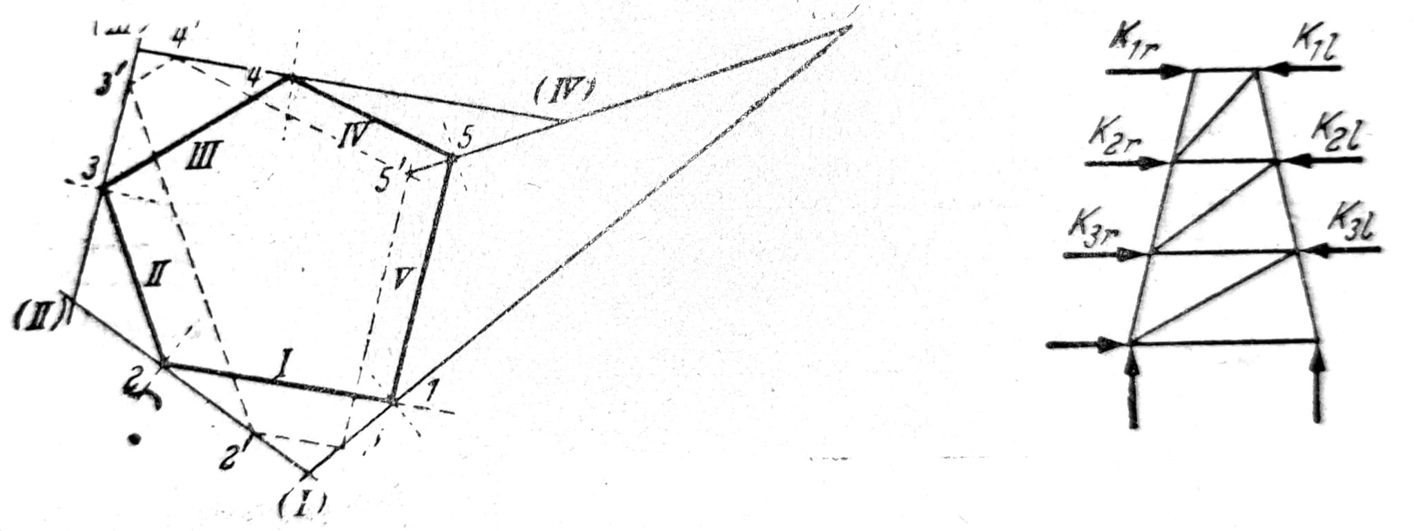
The Schwedler's dome (Fig. 24) and the scalloped grid pyramid (Fig. 25), as a special case of the Schwedler's dome where the meridians have no breaks, with m floors and n sides, consist of m*n meridian rods. S, (m+1)n ring rods R and m*n diagonal rods D. As the number of nodes k=(m+1)n the support is statically determined when the number of supports a = 3k-s = 2n, ie. when each footing of the theme is supported on a linear center of gravity with vertical and horizontal support. If the rods of the lower ring fall off, a stationary bearing with three supports is required in each vertex. The usability of the arrangement of horizontal supports should be examined. The directions of support in fig. 26 are incorrectly chosen because it is possible to draw a non-contradictory pole plan.
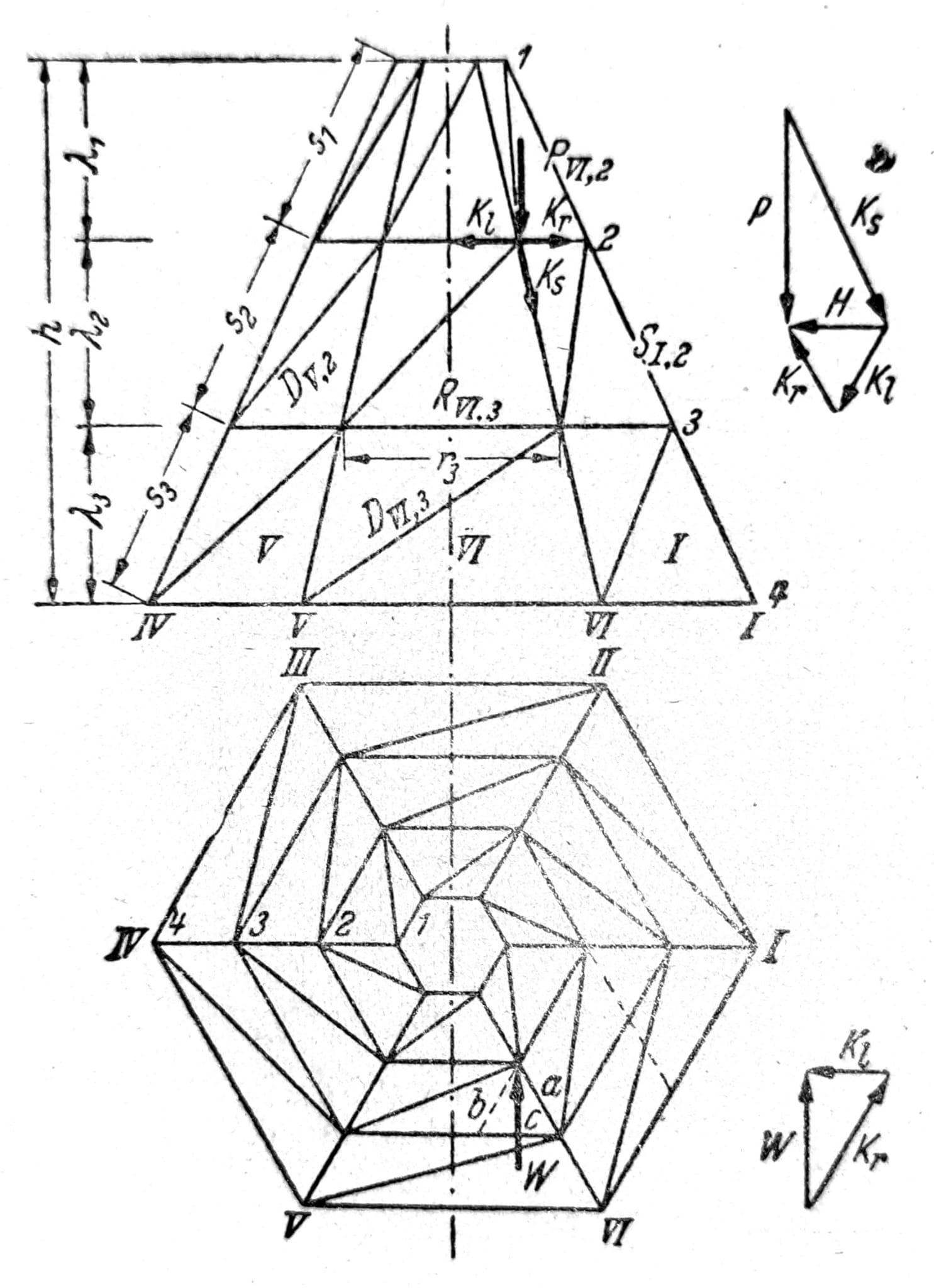
Fig. 25.
Trapezoids formed by meridional rods and ring rods can be stiffened with K-filling. The resulting nodes should be considered as nodes of a flat lattice. Loads may only be transferred via main nodes. The vertical load P that attacks at the node will be decomposed into the component _Ks=Ps/_λ in the direction of the meridian and into the horizontal component _H=Pa/_λ. The horizontal component is further decomposed into components in the direction of the ring rods _Kl=Hc/a=Pc/_λ _i Kr=Hb/a=Pb/_λ.
In the same way, the components Kl and Kr of the arbitrary horizontal force W are determined, so that the load scheme shown in fig. 27. The components of Ks in the direction of the meridian rods are not shown in the figure.
Figs. 26 and 27, respectively.
When the support and the load P are cyclically symmetric, then the forces Kl are equal to the forces Kr, so the diagonals are unstressed while the forces in the meridian rods are:
_S1 = -P1s/_λ; S2 = -(P1+P2)s/λ; S3 = -(P1+P2+P3)s/λ
and in the rods of the ring:
_Ri = Pib/_λ
The calculation of Schwedler’s dome can be carried out in the same way when each floor is understood as a lattice pyramid. Apart from the active forces P and W, the forces in the rods S and D of the upper floor should then be introduced as external forces, respectively. their components in the direction of the meridian rod and ring rods. While in the lattice pyramid the influence of one concentrated force is felt only in the rods of two adjacent plates, in the case of Schwedler's dome its influence extends to a significantly larger number of rods. In fig. 24 are marked rods that are stressed due to the force P in the vertex ring.
Spatial trusses and domes: the stability of these systems depends on the spatial operation, support, geometric imperfections, buckling of rods, stiffness of nodes, temporary compliance and sequence of assembly. A flat sketch or individual equation does not prove global stability, load bearing reserve or safety during lifting.