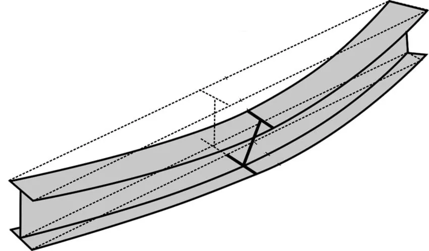
For buckling in bending, the member is bent in one principal plane when equilibrium changes.
But there are also such stability cases in which a rod, i.e. a beam, when equilibrium changes, is not only bent but also twisted (fig. 60a). In beams this phenomenon is called lateral buckling, and in compressed rods, which during buckling are also subjected to torsion, one speaks of buckling under torsion.
For both phenomena, the magnitude of the torsional rigidity C, or the resistance to warping C*, is of decisive importance. The change in equilibrium associated with torsion can therefore be influenced primarily by measures that increase torsional rigidity (appropriate cross-sectional shape, transverse frames, lateral bracing, etc.). On the other hand, bar-like members with an open cross-section are particularly sensitive to buckling under torsion.
Differential equation for lateral buckling
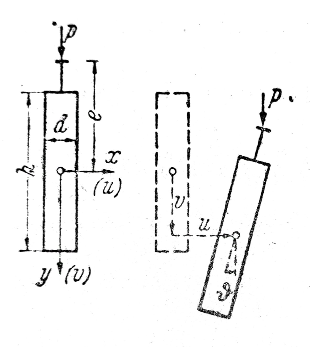
Fig. 1a
Let a straight beam have constant moments of inertia of very unequal magnitude Ix >> Iy. The load lies in the y-z-plane so that the beam will be bent in this principal plane (u=ϑ=0). Experience as well as theory show that this equilibrium position is initially stable, but that it becomes unstable at higher loads. This second equilibrium position is associated with transverse bending in u and with torsion ϑ.
Below, the differential equation for lateral buckling will be derived. The equations for u and ϑ are homogeneous. If the boundary conditions are also homogeneous, then lateral buckling of the beam is possible only for the eigenvalues of the problem, i.e. u and ϑ first remain zero for the beam described above without disturbance. The lateral buckling condition is obtained—similar to rod buckling—by setting to zero the determinant of the coefficients of the homogeneous condition equations for the integration constants. We will see that even in lateral buckling there is a true bifurcation point of elastic equilibrium.
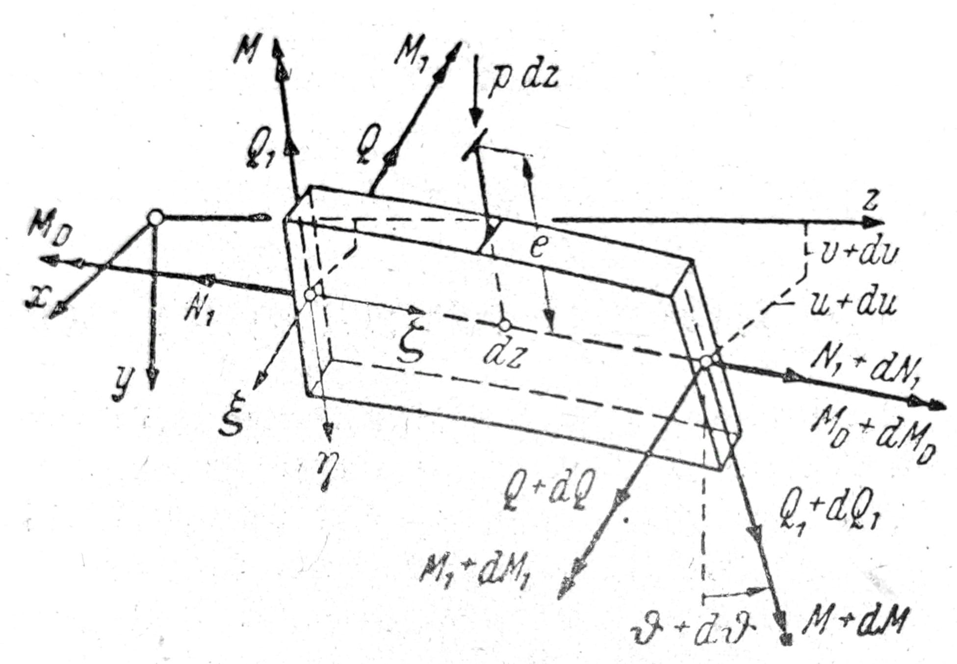
Fig. 1b
In fig. 1b, a beam element of length dz is shown. The stress resultants N1, Q1, M1, as well as the curvature κ__1 depend on the load and are finite quantities. Q, M, MD are zero in the initial equilibrium position and will differ from zero only when lateral buckling occurs. The limiting quantities, which refer to the onset of lateral buckling, are infinitely small, as are the corresponding deformations κ and d__ϑ/dz.
Both end cross-sections of the element dz lie in a normal plane to the doubly curved axis of the bar and will be twisted in these normal planes.
Since we are primarily interested, as in the case of bar buckling, in the magnitude of the critical load, i.e. the onset of lateral buckling, and less in the magnitude of the deformations, we can neglect the products of the quantities Q, M, MD with κ or ϑ’ as small quantities of second order. Therefore, for further simplification, we shall also assume the main curvature κ1 to be infinitesimally small and it will be treated as κ and ϑ’.
Note: The influence of κ__1 is also to be theoretically assessed in a simple special case (constant bending moment M as the load). In most areas of structural engineering, κ__1 can be neglected. We can, for example, imagine that the beam for the given load case is so “pre-cambered” that for the critical load κ__1=0.
From the equilibrium of the force components in the directions ξ, η, ζ and the moment conditions with respect to the same axes, after the aforementioned simplifications one obtains
Q’ + N1u’’ – Q1__ϑ’ + pϑ = 0_,_ (1a)
Q1’ + p = 0_,_ (1b)
N1’ = 0_,_ (1c)
M1’ – Q1 = 0_,_ (1d)
MD’ + Q + M1__ϑ’ = 0_,_ (1e)
MD’ – M1u’’ + pe ϑ = 0_._ (1f)
From eq. (1c, d and b) it follows
N1 = const.,
Q1 = M1’, (2)
p = - Q1’ = - M1’’.
By eliminating Q1 from eq. (1a), one obtains
Q’ = (M1’ ϑ_)’ – N1u’’_. (3a)
From eq. (1e), Q will thus be eliminated, and then u’’ by means of u’’ = (MD’ + pe ϑ_)/M1_
(M+M1 ϑ_)’’ – N1/M1_ ∙ (MD’ + pe ϑ_) =_ 0_._ (3b)
To obtain the differential equation for ϑ, the following relations between moments and deformations will be introduced
M1 = -B1_∙v’’,_ (4a)
M = +B_∙_u’’, (4b)
MD = +C_∙ϑ’ – EC*∙ ϑ’’’,_ (4c)
where B1=EIx and B=EIy denote the bending stiffness of the beam, C the torsional stiffness, and C* the warping resistance. In our further calculations we shall omit the terms with C* for simplicity. If the equations are to be applied, for example, to I-profiles, they must be supplemented accordingly. Neglecting the term v’’ means the same as assuming B1=∞.
If M and MD are eliminated by means of eq. 4, the differential equation for lateral buckling of a beam of constant cross-section is obtained
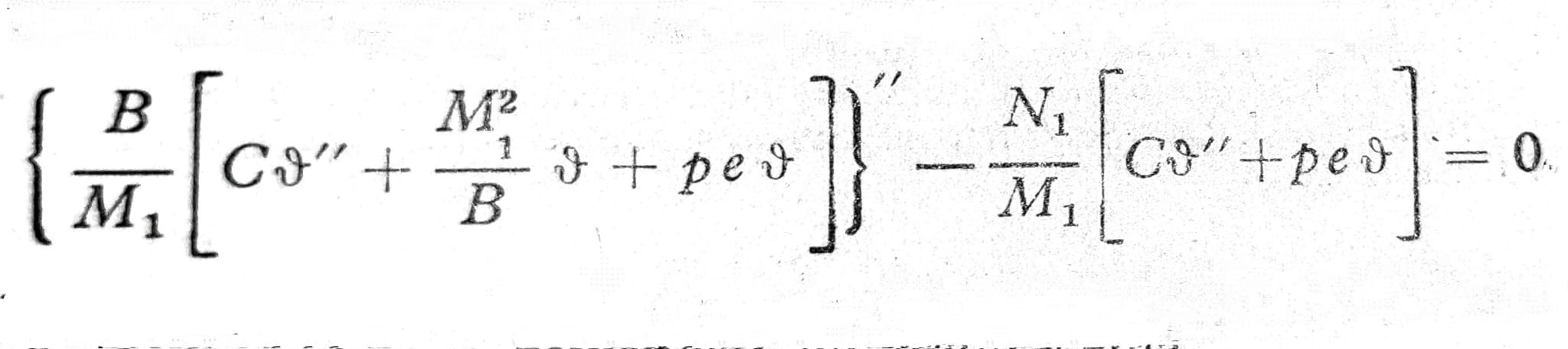
The differential equation (5) is homogeneous and fourth order in ϑ. M1 is a known function of z depending on the load.
Beam with constant bending moment
Let p=N1=0, moreover Mx=ɱ=const. The cross-section is without a flange (compact) and the beam is long relative to the dimensions of the cross-section, so we may set C*=0. Then eq. (5) is simplified, because M1=ɱ, so:
ϑ’’’’ + ɱ2/BC∙ ϑ’’ = 0, (6)
or with the abbreviation λ2_=ɱ__2/BC_
ϑ’’’’ + λ2 ϑ = 0. (6a)
a) Beam with forked supports at both ends

Fig. 2
Support at z=0 and z=l is in the form of forks (Fig. 2), which allow deflections u and v but prevent rotation of the end cross-sections; ϑ=0. Since there is no clamping in the x direction (i.e. M=0, or according to Eq. (4) likewise u’’=0), it follows from the equation for u’’: MD’=0 and thus from Eq. (4c) as the second boundary condition ϑ’’=0.
The general solution of eq. (6a) is
ϑ(z) = A1∙sinλz + A2∙cosλz + A3∙λz + A4. (7)
From the boundary conditions one obtains
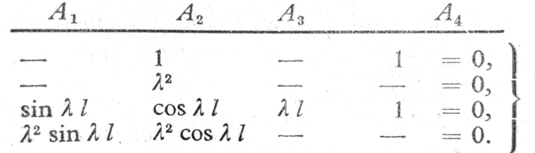
This homogeneous system of equations has:
- Trivial solution A1 = A2 = ∙∙∙ = 0, corresponding to ϑ=0, u’’=0 or u=0, whereby the beam does not buckle laterally.
- Eigen solutions according to Δ=0 or sin λ__l=0. The roots of this lateral buckling condition are λ__l=n__π (with n=1,2,3,∙∙∙) and the corresponding critical moment loads
ɱ__K = _√_BC ∙ _n__π/_l. (8b)
Minimum moment of lateral buckling
min__ɱ__K = _√_BC ∙ π/l (8c)
occurs at n=1. The corresponding solution is obtained by applying eq. (1f):
ϑ(z) = A1 ∙ sin πz/l (8d)
u(z) = C/ɱK ∙ ϑ(z).
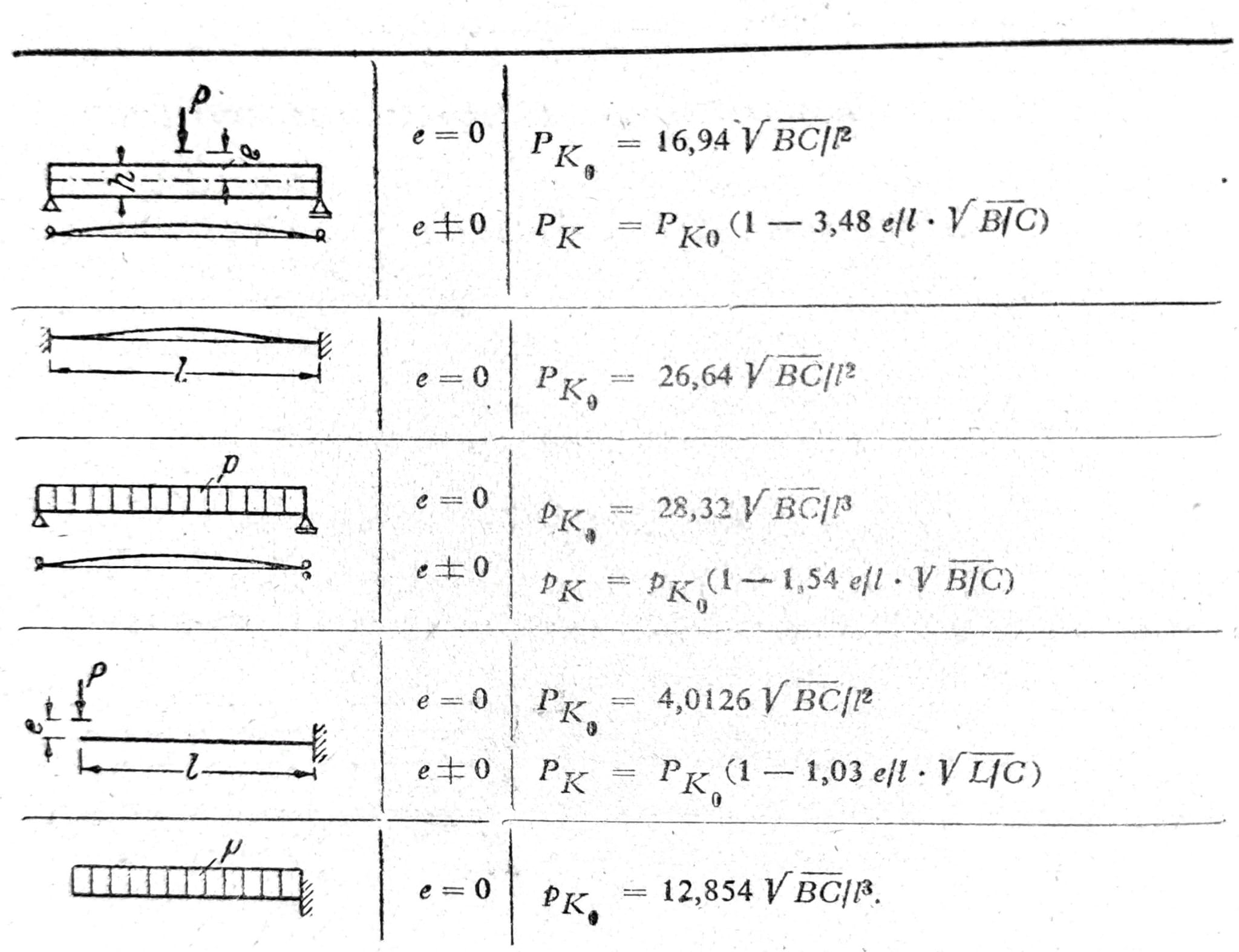
b) Other cases of lateral buckling
c) Lateral buckling due to bending moment and compressive force
For the example shown in Fig. 3, N1=-D (compression), p=0, then C*=0 was set. Then the differential equation (5) simplifies and reads
ϑ’’’’ + λ2 ϑ’’ = 0, (9)
where λ__2 = ɱ__2_/BC + D/B_. (9a)
The solution of the differential equation (9) is given again by eq. (8), only now λ denotes the second value.

Fig. 3
For the example in fig. 3, the contour conditions ϑ=0 and ϑ’’=0 for z=0 and z=l apply as in a). Therefore, the governing equations for A1 are formally the same, as is the lateral buckling condition Δ=sin λl=0. The critical load satisfies the relation λl=nπ (n=1,2,3) and the smallest value is
ɱK2/BC + DK/B = (π/l)2. (10)
For D=0 the moment of lateral buckling is obtained from Eq. (8c), and for pure compressive loading (ɱ=0) the Euler buckling force _DK=B(π/l)_2.
The case shown in Fig. 3 is to be designated as eccentric bending in the y-z plane. The previously considered stability case is therefore buckling out of the plane of bending combined with lateral bending u and torsion ϑ.
If both ends are clamped (ϑ=0 and ϑ’=0) then, from the boundary conditions, using Δ=0, the condition of lateral buckling is obtained
λ__l ∙ sin λ__l = 2(1-cos λl), (11)
with roots λ__l=m__π (m=2,4,∙∙∙) and lateral buckling forces
ɱ__K__2/BC + DK/B = (2_π_/l)2.