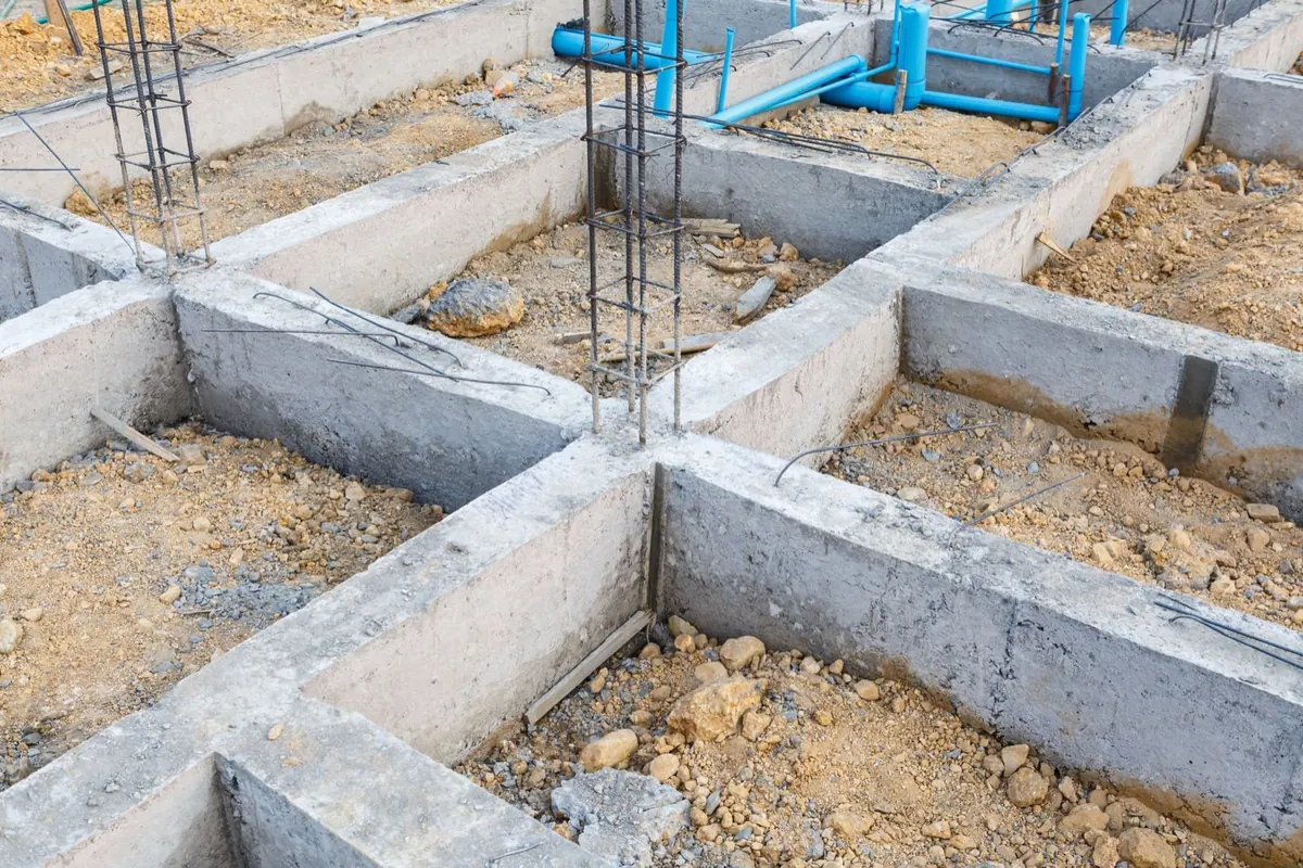
In soil mechanics, the ultimate bearing capacity of soil and the allowable soil load are determined.
The ultimate bearing capacity of soil is the one reached at the moment soil failure occurs. Soil failure occurs when the load by which the foundation acts on the soil exceeds its shear strength. In that case, under the action of the foundation load P, surfaces of least resistance ACD and BCE – sliding surfaces fig. 1 appear, along which the soil is squeezed out laterally and at the same time the soil above the ground surface beside the structure DG and EF rises, while the foundation itself sinks.

Fig. 1. Soil failure under the action of foundation load
The shear strength of soil increases with the foundation depth t, because the weight of the overlying layers reduces the possibility of lateral squeezing. Accordingly, deep foundations are less likely to cause soil failure, whereas shallow foundations are prone to failure. Likewise, wide foundations are less likely to cause soil failure because the slip surfaces are deeper.
Permissible load of soil is the load that may be allowed to act on the soil without causing soil failure under the most unfavorable possible conditions. The permissible soil load is determined on the basis of the ultimate bearing capacity of the soil by applying a safety factor. The size of the safety factor depends on several factors, among which the most important are the accuracy of the physical characteristics of the soil, the possibility of changes in the values of the elements of the soil’s internal resistance, especially cohesion, whose value can vary widely under the influence of water in the soil, then the influence of possible other factors, such as loading conditions (the possibility of sudden and dynamic loading), foundation depth, and the width of the footing.
Soil bearing capacity can be determined on the basis of soil failure, which gives the ultimate bearing capacity. The ultimate bearing capacity of soil means the magnitude of the load that causes failure. There are two ways of determining ultimate bearing capacity on the basis of soil failure: mathematical solution and test loading.
Mathematical solution
Many scientists have tried to find a mathematical solution for determining the ultimate bearing capacity of soil, based on knowledge of the influencing factors and under different assumptions of failure conditions. The influencing factors are the physical characteristics of the soil, determined by laboratory tests on undisturbed soil samples, the groundwater condition, foundation depth, the size and shape of the loaded area, as well as the method of loading, i.e. uniform or nonuniform, concentric or eccentric loading of the soil. Assumptions about failure conditions are based on plasticity theory and elasticity theory. However, modern methods for determining soil bearing capacity are based on plasticity theory, combined with certain simplified assumptions.
Here we will present several well-known calculation methods for determining the ultimate bearing capacity, i.e. the allowable load-bearing capacity of soil.
Prandtl-Caquot pattern
If the footing AB is founded at a depth t below ground surface, at this depth a contact pressure p acts due to the foundation load and a lateral pressure p=γt due to the weight of soil above the footing level up to the ground surface (Fig. 2).
Under the direct action of the weight of the foundation, at the moment the ultimate bearing capacity of the soil is exceeded, the true sliding surfaces AC and BC appear, forming an angle α = 45° + ϕ/2 with the loaded surface. These sliding surfaces form the active earth prism ABC.

Fig. 2. Sliding surfaces in the form of a logarithmic spiral under a centrally loaded footing according to Prandtl-Caquot
Under the action of the active earth pressure, lateral passive earth prisms ADD1 and BEE1 are formed, which it tends to push upward along the slip surfaces DD1 and EE1, at an angle of 45°-ϕ/2 to the horizontal. Between the zone of active and passive earth pressure there is a zone of radial shear ACD or BCE, in which, when the limit equilibrium is exceeded, sliding occurs along curved slip surfaces. Résal calculated that the slip surfaces in the zone of radial shear are in the form of a logarithmic spiral with poles at A or B, whose equation is r=r0 eπ tg_ϕ_
The following assumptions were made for determining the limiting soil load:
- that the foundation is smooth, i.e. friction between the footing and the soil is neglected;
- that the shear strength of the soil along the surfaces D1M and E1N does not exist, i.e. it is neglected;
- that the unit weight of the soil beneath the footing γ=0, that is, the effect of the soil weight beneath the footing is neglected, in the zone of plastic equilibrium.
The Prandtl-Caquot formula reads:
The ultimate soil bearing capacity is

If we put:

the ultimate bearing capacity of cohesive soil is qf = γtm + cm1.
For different values of the soil internal friction angle, the values for m and m1 are given in Table 1.

Table 1. Values of the coefficients m and m__1 for different values of the soil internal friction angle
The allowable soil load is qa = pdozv = qf/F where F is the safety factor. For the application of the Prandtl-Caquot formula, F = 4 is adopted, so qa = qf/4.
Terzaghi’s formula
Terzaghi proposed a semi-empirical formula for calculating the ultimate bearing capacity of soil under strip, square, and circular plate loading. He considered a foundation founded at a depth Df below ground surface, with width B (fig. 3), and assumed that there is friction between the foundation footing AB and the soil, which opposes lateral squeezing of the soil, and that the slip surfaces AB and BC enclose an angle of internal friction with the loaded surface.

Fig. 3. Ultimate bearing capacity of soil according to Terzaghi
As a result, the soil in the earth wedge ABC, enclosed between the foundation AB and the sliding surfaces AC and BC, remains in a state of elastic equilibrium and behaves as part of the foundation. The prism ABC cannot be pushed in until the pressures on its sides AC and BC are equal to the passive earth pressure of the side prisms, which means that when the limit state of equilibrium is exceeded, the resulting soil pressure q acts at an angle ϕ to the normal on the sliding surface, i.e. in the vertical direction (fig. 3). Since under the action of the load the wedge moves vertically downward, the problem of equilibrium in the soil is reduced to determining passive earth pressure. However, since the exact calculation of soil bearing capacity by this method is complicated, Terzaghi proposed a simplified solution. Terzaghi’s formula for calculating the ultimate soil bearing capacity _q_f reads
- For a strip footing
qf = cNc + γ1 DfNq + 0,5 γ2 BNγ
where c is the soil cohesion
γ1 volumetric weight of the soil above the foundation base
Df foundation depth below ground surface to the base of the foundation
γ2 unit weight of the soil below the foundation base
B width of the footing.
Nc, Nq, Nγ are bearing-capacity factors, dependent on the angle of internal friction of the soil. The values of this factor are given by the following formulas:
Nq is the factor due to the weight of the side layer of soil to the foundation depth: Nq = tg2 (45° + ϕ/2) eπ tg_ϕ_
Nc is the factor due to cohesion: Nc = (Nq – 1) ctg_ϕ_
Nγ is the factor due to the self-weight of the soil wedge below the footing, i.e. below the width of footing AB. Brinch Hansen recommends the following approximate value for this factor: Nγ ≈ 1,8 (Nq – 1) tg_ϕ_

Fig. 4. Distribution of stresses received by the soil under vertical centric loading of the foundation
Because of the small difference in the unit weight of soil, it is often assumed that γ1= γ2= γ. According to the foregoing equation, soil bearing capacity depends (fig. 4) on: the cohesion of the foundation soil c, the surcharge on the soil beside the foundation γ1 D_F, and the self-weight of the soil of the active sliding prism of width B.
However, while the distribution of stresses transmitted to the soil due to cohesion c and founding depth Df is uniform across the entire width, i.e. rectangular, the distribution of stresses transmitted to the soil due to the effect of width B is triangular, i.e. the greatest stresses are carried in the center of the foundation and decrease toward the edges where they are equal to zero.

Fig. 5. Bearing-capacity factor diagram as a function of the soil’s angle of internal friction according to Terzaghi
For different values of the angle from 0 to 40°, Terzaghi prepared diagrams of bearing-capacity factors (fig. 5). However, the bearing-capacity factors Nc, Nq and Nγ (solid lines in fig. 5) can be adopted only in the case of dense and firm soil. If the soil is loose or more compressible, then the bearing-capacity factors N’c, N’q and N’γ (dashed lines in fig. 5) should be adopted, which give 2/3 values of the friction resistance. In addition, in this case 2/3 values of the cohesion c obtained in the laboratory should be used, so that in that case we have qf = 2/3 cN’c + γ1 DfN’q + 0,5 γ2 BN’γ.
2. For a rectangular footing
qf = 2/3 (1+0,3 B/L) cN’c + γ1 DfN’q + 0,5 γ2 BN’γ where L is the length of the footing
3. For a square earth footing
qf = 2/3 1,3 cN’c + γ1 DfN’q + 0,4 γ2 BN’γ
4. For the circular base footing
qf = 2/3 1,3 cN’c + γ1 DfN’q + 0,6 γ2 rN’γ where r is the radius of the footing.
For the calculation of the allowable soil load, the safety factor F is adopted: qa = qf/F. The value of the safety factor ranges from 2 to 3 according to soil and load conditions.
Application of mathematical formulas
The application of mathematical formulas for determining the allowable soil load requires knowledge of the geomechanical characteristics of the soil, namely cohesion and internal friction at the foundation depth, and the unit weight of the soil above and below the foundation base. If the foundation soil lies below the groundwater level, buoyancy must also be taken into account when determining the unit weight of the soil.
For greater soil loads and larger structures, when the obtained value of allowable soil pressure is fully utilized on the basis of mathematical formulas, the calculation of soil bearing capacity should be accompanied by a settlement calculation. The calculated soil bearing capacity is accepted only if the settlement calculation yields a settlement smaller than the permissible one for the given type of structure. If the settlement obtained by calculation is greater than the permissible value, the calculated value of allowable soil pressure determined by calculation formulas is not accepted; instead, the foundation method must be changed so as to obtain a smaller settlement, within the limits of permissible settlement for the given structure design.

Fig. 6. Effective foundation depth D__f
In the mathematical formulas for determining the ultimate bearing capacity of soil, the friction of the foundation base has not been taken into account, although it also contributes as resistance to the action of load, provided the foundation is in firm contact with the soil on the sides. The resistance due to skin friction should not be taken into account, because true skin friction exists only in piles driven into the ground, whereas for footings the skin friction is negligible, since the footings are constructed in pre-excavated pits.
The application of mathematical formulas that do not take the foundation shape into account gives the closest results for strip foundations, i.e. when the foundation length is more than twice its width. Tests have shown that for square or circular footings, failure occurs at a limit load that is 10-30% higher than that calculated by mathematical formulas. Triangular footings have a lower bearing capacity than strip footings, and ring-shaped footings have the lowest bearing capacity, if they are not filled.
The foundation depth Df is calculated as the effective foundation depth below the base soil to the footing bottom (Fig. 6). In the case of foundations below underground spaces, the effective foundation depth Df differs from the foundation depth below ground level as well. In such cases, for calculating the limit and allowable soil load, Df should always be adopted, since above the base soil there is air, which does not oppose the lateral displacement of the soil under the action of the foundation load P.