
Capillarity
The phenomenon of capillarity
If we immerse a narrow glass tube in a vessel with still water without flow, the water in the tube will rise to a height hk above the level N in the vessel, and the water surface in the tube will form a meniscus m (fig. 1_a_). The narrower the tube, the greater the height of capillary rise of the water hk.
The capillary rise of water is attributed to the lifting force of the meniscus m, and is explained by intermolecular attractive forces between the molecules of water and glass and by surface tensions between the walls of the narrow tube and the surface of the water.
At the contact between the wall of the glass tube and the water surface, the capillary force R acts in the direction of the tangent to the meniscus surface m, and is expressed as force per unit length, in p/cm. By resolving the force R into a component J parallel to the wall surface and a component P normal to the wall, we obtain the uplifting force of the meniscus (fig. 1_a_): J = R cosα.
The angle α which the force R makes with the surface of the wall is called the capillary angle, and its value ranges from 0 to 90O. If the water in the capillary tube and its walls are completely clean, then α=0, the meniscus surface is semicircular, and the lifting force J = R is maximal (fig. 1_b_). If the water contains fats or organic acids, or if the walls are greasy, then α = 90°, no meniscus forms, and there is no capillary rise of water.
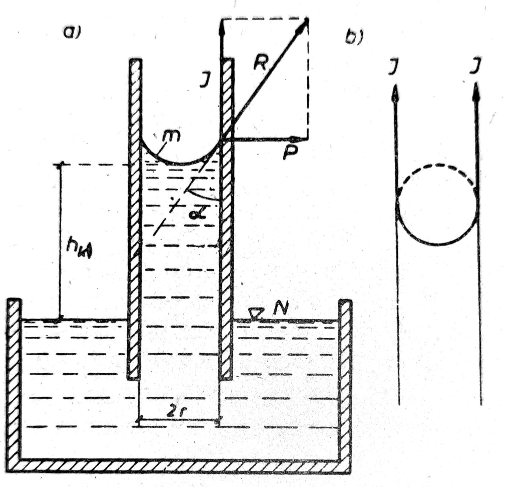
Fig. 1. Capillary rise of water and the action of capillary forces
The uplifting force J = R cos α is obtained from the condition of equilibrium, according to which the total uplifting force J around the entire perimeter of the meniscus, that is, of a capillary tube of radius r, holds the water column in the tube at a height h__ₖ:
R cos α · 2π_r_ = π_r_² h__ₖ γ__w
where γ__w is the unit weight of water.
From the foregoing equation we obtain the upward capillary force:
R cos α = (r · h__ₖ · γ__w) / 2
that is, the height of capillary rise:
h__ₖ = (2_R_) / (r · γ__w) · cos α [cm].
Warm capillary water rises in the capillary tube to a greater height than cold water because of its higher viscosity. Therefore, for the same capillary rise height h__ₖ, the force R cos α is smaller for warm capillary water than for cold. According to tests carried out for different water temperatures t under identical conditions, the following values of the lifting force R cos α were obtained:
| t = | 0° | 10° | 20° | 40° |
|---|---|---|---|---|
| R cos α = | 0,0756 | 0,0742 | 0,0727 | 0,0695 p/cm |
Water in a capillary tube is under tensile stress, because the force R cos α lifts it upward, while gravity pulls it downward. However, the walls of the capillary tube are under compressive stress under the action of the capillary force R.
Capillarity in soil
Capillarity also exists in soil, where capillary tubes form pores that are interconnected in all directions. The finer the soil, the finer the pores and the greater the capillary rise height. This height also depends on the structure of the soil. However, pores in soil may vary in size, and in that case the capillary rise height also varies. If, during rising, capillary water reaches “wider places,” i.e. a larger pore than corresponds to the upward force for the diameter of the narrower pore at the attained height, then further capillary rise depends on the size of that larger pore. In this case we have the active capillary rise height h__ₖₐ, which depends on the largest pores. Conversely, when, as the groundwater level drops, the capillary water descending from above encounters “narrower places,” it will remain at that depth and will not descend further. In that case we have the passive capillary height h__ₖₚ, which depends on the smallest pores.
According to soil porosity and structure, closed and open capillary water are distinguished.
Closed capillary water is connected with the groundwater table and, as it rises, pushes the air ahead of it into the upper zone of the soil. As a result, the amount of air in the upper zone increases, and with it the air pressure in the pores of that zone. The air pressure thus created opposes capillary rise, so the height of capillary rise is lower. This case occurs in the lower layers of soil, directly above the groundwater level, where the pores are fine and, during capillary rise, the water completely fills all the pores.
Open capillary water is also related to the groundwater table, but is located next to pores filled with air. This case occurs in the upper part of the soil, where the pores are of different sizes so that water completely fills only the small pores, while air is present in the neighboring larger pores. During capillary rise, the water displaces air from the small pores into the adjacent larger ones, so that in the upper zone above the water column in the capillary no air pressure is created, and open capillary water rises to a greater height than closed capillary water.
The zone in which there is closed or open capillary water is determined on the basis of the amount of water w in the soil.
In closed capillary water all pores are filled with water, which means that the amount of water in the soil w = wZ, i.e. the degree of saturation S__ᵣ = 1,0.
In open capillary water, the fine pores are completely filled with water, while the larger pores are partially filled with water, namely by a water film that surrounds the solid particles and by angular water (fig. 2) at the contact points between solid particles, and partially by air; in this case w < wZ, i.e. S__ᵣ < 1,0.
The heights of capillary rise h__ₖ for individual soil types are determined by laboratory testing. The average heights h__ₖ for individual soil types fall within the following ranges:
| Type of soil | hₖ |
|---|---|
| fine sand | hₖ = 0,05 - 0,5 m |
| dust | hₖ = 0,5 - 5,0 m |
| clayey soil | hₖ = 5,0 - 15,0 m |
| clay | hₖ = 15,0 - 50,0 m and more |
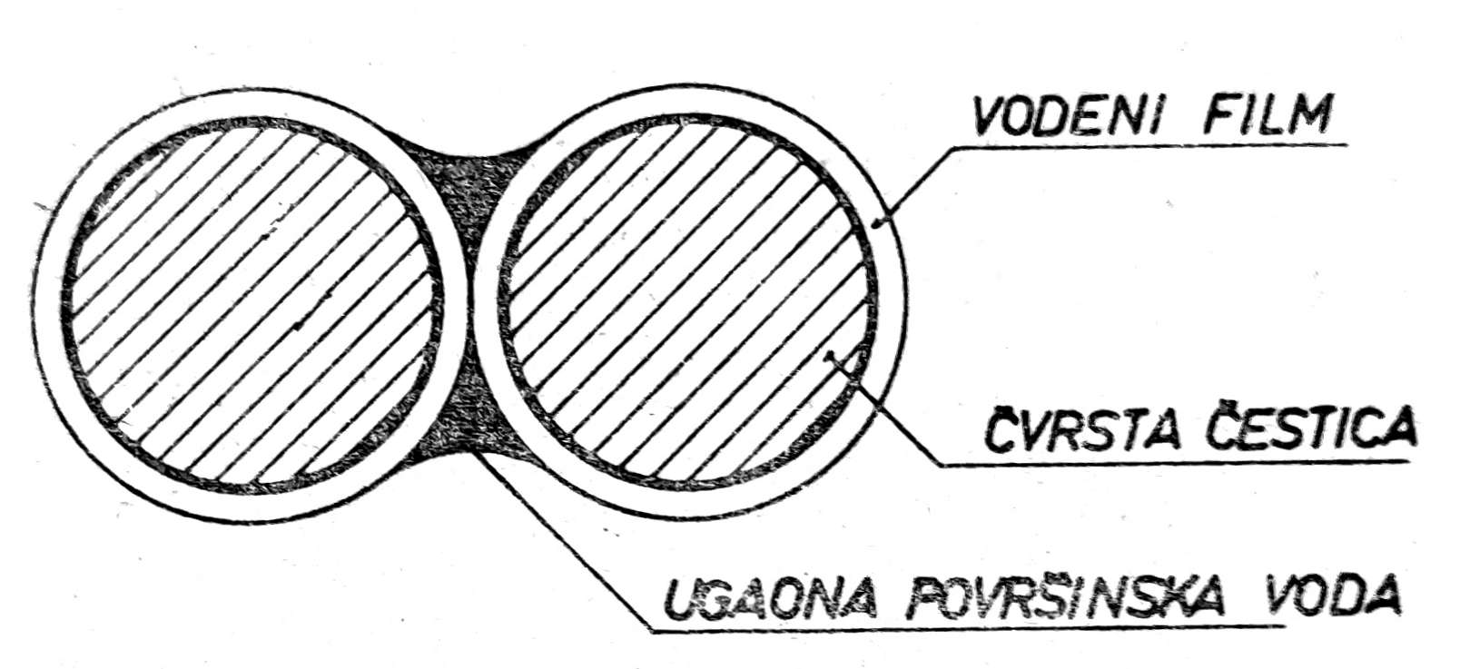
Fig. 2. Water film and angular surface water
In soil, the capillary force R acts by pressing on the solid particles so that so-called apparent cohesion is created between them, acting as a certain binding force between the solid particles. However, apparent cohesion exists only as long as capillary rise of water exists in the pores of the soil. By immersing the soil in water, the pores become saturated with water and the apparent cohesion ceases to exist.
Apparent cohesion explains the phenomenon that fine sand, which is loose in the dry state, acquires a certain binding ability in the moist state, so that it can be modeled, which is not possible with dry sand.
It is well known that sand (provided it is not sludge or dust) on sea beaches, when wetted by waves, has such a good load-bearing capacity that a bicycle or car can be driven over it, whereas farther away, where the waves do not reach, the same sand is dry and the wheels sink into it, making any driving impossible.
PERMEABILITY
Flow of water through a permeable mass
Let us consider communicating vessels A, B, C, D, and E (Fig. 3), part of which, from a to b over a length L, is filled with a permeable mass, for example sand. If we pour water into one end of the communicating vessels up to level N₁, then the water level in the communicating vessels will be different, i.e. it will decrease with the length of the path traveled by the water.
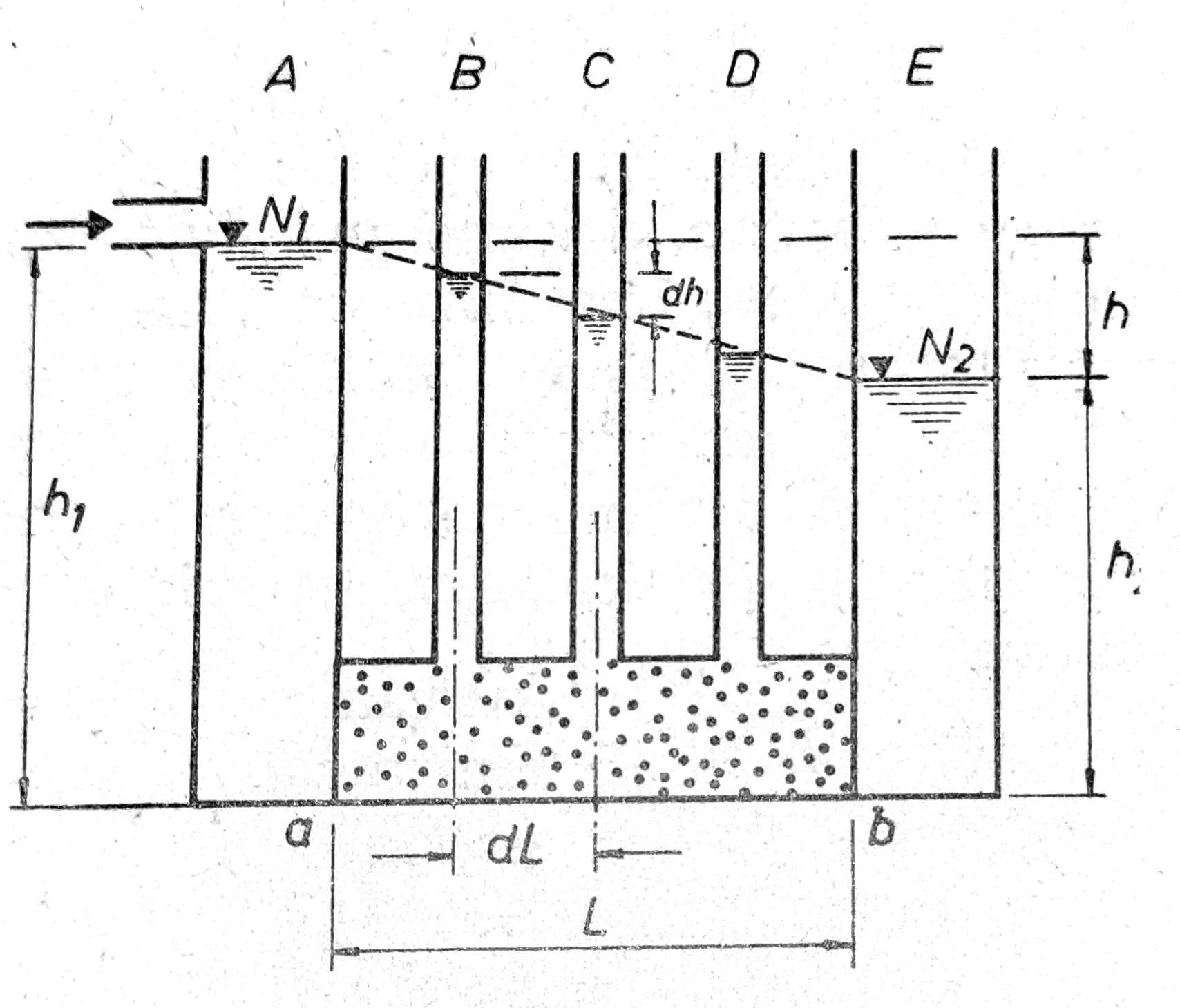
Fig. 3. Flow of water through a permeable mass
When the height of the water column h₁ has been reached in front of the filter, behind the filter there will be h₂. The difference between levels N₁ and N₂ is then:
h = h₁ − h₂
The difference h represents the lost hydrostatic pressure, which is consumed in overcoming the resistance to water flow through the filter. This phenomenon was established by the French scientist Darcy as early as 1856. He then also set the following formula for calculating the velocity of water flow through a permeable mass:
V = k × (dh/dL) = ki
where:
- V = the velocity of water flow through the permeable mass, [cm/sec],
- k = the permeability coefficient, which depends on the properties of the soil [cm/sec],
- dh = the length obtained when the height h is divided into a large number of thin layers [cm],
- dL = the length obtained when the length L is divided into the same number of lengths as the height h, [cm].
The ratio dh/dL = i is the ratio of the head lost in seepage to the distance traveled by the water and is called the hydraulic drop, hydraulic gradient or also the piezometric slope. This latter name comes from the pipes B, C and D, which are called piezometric tubes. The preceding formula is called Darcy’s law of water flow through a filter.
The total quantity of water q passing through the filter of cross-sectional area A in a given time t is
q = kAti,
from which it follows
k = q / (Ati), or k = qL / Ath,
where i = h / L = hydraulic gradient over the length L (if it is linear).
The coefficient k expresses the permeability of the soil at a temperature of 10°C.
k = V / i [cm/sec]
The velocity of water flow through the soil is obtained from the formula
V = q / A [cm/sec],
where q = the amount of water flowing through the soil in cm³ per second, at a temperature of 10°C, A = cross-sectional area of the soil through which the water flows, [cm²].
Darcy’s law applies to laminar water movements, i.e. calm, vortex-free movements, and to low velocities.
The filter velocity V is the average speed of water movement through the soil and it does not correspond to the actual flow velocity of the water, which is higher. When water flows through a filter, equal elements of head loss dh are very often expended over unequal lengths of the water path dL, so the hydraulic gradient varies from one point in the soil to another.
Soil permeability depends on the size of the pores in it. If the soil is subjected to loading, the pores decrease and permeability becomes lower. Accordingly, for one and the same soil, the permeability coefficient k is directly proportional to the degree of porosity, that is, to its void ratio e. However, for different types of soil, porosity expressed by the void ratio e cannot be a measure of permeability, because this permeability depends not so much on the total porosity of the soil as on the size of the pores in it. Thus, for example, gravelly sand with a porosity of e = 0,25 has a very high permeability, k = 2–3 cm/sec, whereas soft clay, with a porosity of 60%, void ratio e = 1,50, has low permeability, k = 10_⁻⁶ to 10⁻_¹¹ cm/sec.
The permeability coefficient k can be determined by calculation, by laboratory and by field tests.
Determining the coefficient by calculation is based on the granulometric composition of the soil. To determine the coefficient k, it is assumed that the solid soil particles are spherical in shape, which does not correspond to reality, especially in cohesive soils. For this reason, the values of coefficient k determined in this way are not accepted as accurate.
Determining the coefficient k by laboratory tests is the most widespread method and is performed on undisturbed soil samples. However, the accuracy of the coefficient k determined in this way depends on several factors, such as whether and to what extent the sample used in the test represents the permeable layer in the soil, then on the state of undisturbance of the sample in the testing apparatus, and on the manner in which the test is carried out. By testing a sufficient number of samples that will represent the given soil, by taking the sample in the field in the cylinders of the testing apparatus itself, and by an appropriate test procedure, it is possible to obtain approximately accurate values of the coefficient k that can be used as satisfactory.
Determining the coefficient k by field testing gives the most accurate values, because it fully corresponds to the composition and stratification of the soil in which it is found. However, this method of determining the coefficient k requires a great deal of time and high costs, which is why it is rarely performed and only in cases where its exact value is absolutely necessary.
According to our regulations for foundations, soils are considered to be those whose permeability coefficient:
- k < 10_⁻_¹¹ cm/sec — almost impermeable
- k < 10_⁻_⁹ — very slightly permeable
- k < 10_⁻_⁷ — slightly permeable
- k < 10_⁻_⁵ — medium permeable
- k < 10_⁻_³ — more permeable
- k > 10_⁻_³ — very permeable