Important technical and security note: This is archived text, originally published by 2018. year, and not a modern manual for metalworking. Cutting, filing and drilling can cause cuts, sharp and hot chips, flying tool parts, entanglement in clothing or hair, noise, dust and eye injuries. The workpiece must be stably clamped with a suitable device, the tool must be correct and intended for the material, and eye, hearing and respiratory protection must be chosen according to the risk assessment. Gloves and loose clothing must not come near the rotating tool. Pipes and closed profiles must be empty, unloaded and of known content before processing. The choice of blade, file, drill, speed, feed and coolant or lubrication must follow the current instructions of the tool and material manufacturer. The original measures and procedures on this page are not a substitute for training, protective devices or a qualified contractor.
Metal processing is not part of the new public offer of Savo Kusić. Current focus is wood windows, wood-aluminum windows, custom windows and doors. For a window or door project, you can send request for quote.
Saw cutting
When describing woodworking work, there was a lot of talk about the process of cutting wood. Basically, it is almost the same process of cutting metal with a hacksaw. We hold the saw in a horizontal position so that the spikes of the teeth grip the metal (picture 1).

Figure 1 — Saw blade position and tube rotation during manual cutting
A special case is cutting a pipe. If the saw has cut through the wall of the pipe, its teeth cut both sides of the pipe at the same time, and this often causes the teeth to break. To avoid these inconveniences, when working, we turn the pipe in the mangels so that the saw cuts only one side. If we are cutting a thin-walled pipe, we insert a round wooden bar into it so that it fits tightly against the walls of the pipe. If the pipe walls are less than 1mm thick, we cut them with a small hand-held carving saw.
The description of turning the tube and inserting a wooden rod is preserved as a historical procedure, but it is not a universal method. Thin pipe is easily deformed or dislodged from the clamp, and unknown pipe may contain pressure, flammable debris, or hazardous coatings. The method of clamping and cutting must correspond to the exact pipe, material and selected tool.
Filing
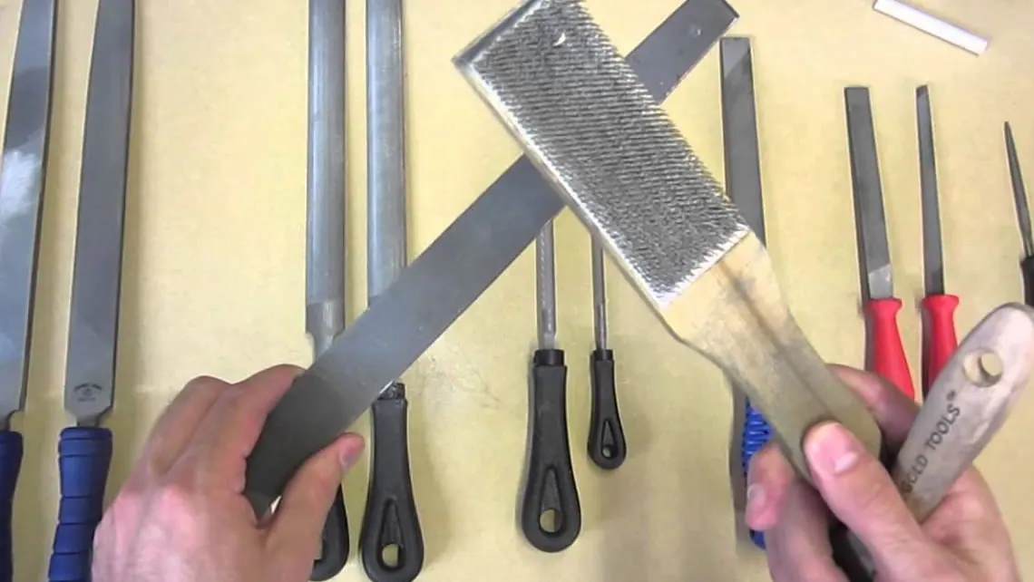
Even today, locksmiths joke with each other about practical work students when they send them to the warehouse to look for file grease. Oil and grease are known to be the enemies of files, as they make it impossible to separate the small particles of chips. The task of this widely used tool is to file with the help of pressure with its teeth and at the same time remove an unnecessary layer of metal. If there is a lubricant under the small teeth, then they do not “bite”, but slide on the surface of the object to be processed. It follows that the file must be kept free from grease. For different processing of metal surfaces, different types of files are used, which differ in size, shape and cross-section.
The length of files ranges from 100 to 500 mm, and they can be flat, round, semi-round, triangular and square.
According to the type of toothing, we distinguish between coarse, semi-fine and double-fine files. When a file wears out, its serrations can be renewed. Such files are cheaper. The file ends with a sharp point that is built into the wooden handle.
In the home workshop, it is necessary to have files of various cross-sections, e.g. flat, semi-round and one piece each of coarse and very fine file of 150 mm length. Another set of files with three serrations, length 120 mm (working surface of the file) is necessary: flat, square, triangular, round and knife file. These files do not have special wooden handles, because they are so small and fine that they can be directly grasped with the hands. It is not superfluous to provide a special file for filing soft metals (aluminum, lead).
When we file an object, we hold the tip of the file with our left hand, and the handle with our right hand, pressing the file we pull it along the same plane and in this way file (picture 2). We place the workpiece in the vise at elbow height.

Picture 2 — Position of the file and the workpiece in the vice
The method of filing metal is not much different from the already known way of filing wood. According to the need to shape the workpiece, we use files of the appropriate profile. When filing the edge of an object, we hold the file in a horizontal position and at an angle of 45° in relation to the edge whose end is closer to us, going towards the other end. Shaping the edges of the cut, at a right angle, is done with a flat file (the plane of the tool is horizontal), and the thicker layers are removed with the wider part of this file (picture 2).
When using a file, the space between the teeth fills up and the tool grips less and less. The file should be coated with ordinary chalk to prevent clogging. Chalk powder prevents metal shavings from getting stuck between the teeth. If, however, this happened, we will remove the shavings with a brass file brush. When we store the files, we never leave them on top of each other, because friction ruins the grooves. It is best to hang them after use so that the handle is in a vertical position. Since we must not coat them with oil, we wipe them and leave them in a dry place so that they do not corrode.
Finally, just one more tip: the file does not “catch” steel tools and hard metals. They can only be “weakened” with a sanding board.
The working handle must be undamaged and correctly placed on the file; the bare point of the file must not be used as a handle. The workpiece should be clamped stably, and metal dust and shavings should be removed with a brush or other dedicated tool, not by hand or by blowing. The grinding wheel claim should not be applied without selecting the appropriate machine, abrasive, guard and protection against sparks and dust.
Drilling
Under the category “carpentry in the house” we have already talked about spiral drills for metal drilling in detail, so now we will point out only a few working operations.
We should pay attention that during drilling, the axis of the drill does not change its position, but remains in the same position as it was at the beginning of metal drilling. Drilling arc axis holes is still not feasible today, so it often happens that experienced craftsmen send their students not only for file lubricant, but also for drill bits for drilling arc holes.
Drilling should not be started without first marking the drilling site with a marker - »kirner« (picture 3). When drilling a deeper hole, we take the drill bit out of the hole several times to remove the chip. If the drill gets hot, we cool it with soap dissolved in water, and never with any oil. We will remove the broken drill bit from the hole, with pointed pliers, by turning the pliers in the opposite direction of the movement of the spiral groove. If the drill has pierced the workpiece, and the broken part remains in the hole, we can knock it out with a pointed marker. Thin twist drills break very easily under higher pressure. The weight of the drill is enough of a burden for them. When buying, you should make sure that the drill can fit in the chuck.
Recommendations about soap, no oil, removing a broken drill bit, and punching out a part with a marker are historical statements, not a general safety rule. The coolant depends on the material and the operation; before removing a jammed or broken tool, the machine must be completely stopped and disconnected from the power supply. A damaged drill bit and an unstable piece can move suddenly, so the procedure requires judgment and the right tool.

Image 3 — Preparation of the edge and dot marking of the drilling site
What the drilled hole will be depends a lot on the previous preparation of the workpiece. Therefore, we will show several working operations during preparation.
Before drilling, any metal, we must accurately mark the place of drilling with two lines that intersect at right angles. The center of the drilling is located at the point of intersection of these lines. It will be easiest to draw lines if they are parallel to the edges of the workpiece, and we can do this by using a steel angle - a knife angle. We mark the places for drilling that are equidistant from each other with a metal compass, not a metal scale. Let’s mark the first two drilling places and draw a longer straight line through them. With a metal ruler, we transfer the distance between the first two points to the indicated line. And so we mark the rest of the drilling sites.
We deepen the marked places with a marker so that the tip of the drill does not slide. We place the dot marking marker with its tip in a certain place, but slightly inclined, and after straightening it, we hit the free end with a hammer.
The working bodies, before drilling, should be well fixed. There are several possibilities for this. The steel “U” profile is fixed to the work table by means of a stepped washer, a screw or a piece of “U” profile, which has been cut with a saw in a suitable way.
We can drill the edge of rectangular steel - winkle. We first file the edge of the angle iron and mark the place of drilling with a needle and dot marking tool, which allows drilling of the angle iron.

Image 4 — Supporting a round drill bit
To fix the rods with a round cross-section, it is worth making a special clamp made of bent flat iron (can also be a blind guide) which has threads with a nut at the ends (picture 4). We can accept pipes with a stirrup with a screw. This method allows us not only to drill but also to cut pipes. We will prevent the movement of the angle iron if we place one leg of the angle in the cross-cut formed cut. If the angle is short, we accept it with a clamp and drill. We drill a short flat iron by clamping it with a clamp. (picture 5).

Image 5 — Special clamp for holding the workpiece
The hole should not be too deep, if we do not want to drill the workpiece. We can achieve this most easily if we put one ring with a coil on the drill, in order to adjust the depth of the hole, i.e. attach the depth gauge to the drill bit. Before drilling holes with a larger diameter (e.g. 8 mm), we drill the workpiece with a smaller diameter drill (e.g. with a diameter of 4 mm). In this, the thicker insole will not crawl. We pre-drill the hole for the screws, and then for the head of the screw. Burying the screw head is done with a previous widening and deepening of the hole. The diameter of the countersink should be slightly larger than the diameter of the screw head.
Depth stop, pre-drilling, drill diameter and countersinking of the screw head are selected according to the machine, material, joint geometry and manufacturer’s request. The improvised ring must not detach or catch on rotating parts. The measurements from the example remain part of the original text, but are not a universal specification.
The location of the drill bits has a great influence on their life. The simplest solution for housing the drills is one lath of greater thickness, on which we vertically drilled places with our drills to accommodate them (although this wood drilling does not use an insert, one use does not damage it).
In the holes drilled in this way, after cleaning and fine lubrication, we place the drill bits vertically with the roller end on the bottom. The drill frame must not lean to the side, but it is recommended that the slat is screwed to the bottom or side of the tool shelf.
In the picture 6 we will show the angles of the twist drill applied for different type of work material as well as the way of shaping the blade and the roller part.

Image 6 — Historical representation of the geometry of the drill tip and taper holder
The angles and divisions of the drills shown are preserved as a historical illustration. The geometry of the tip, the material of the drill, the grip, revolutions, feed and cooling are chosen according to the specific drill, machine and work material; the drawing is not sufficient for selecting or sharpening the tool.