Important professional and safety note: This is an archival expert review, not a design, static calculation, assessment of an existing bridge, or instructions for construction, inspection or rehabilitation. The original divisions, spans, ratios, stresses, materials, joint details and construction solutions have been transferred without professional verification and should not be used as a modern specification. Designing and works on bridges require authorized designers and contractors, current regulations and standards, geotechnical and hydrological data, calculation of permanent and variable effects, fatigue, wind, temperature, seismicity, stability, foundations, assembly conditions and robustness, as well as testing of materials, corrosion, joints and the actual condition of the structure. Access to the structure, working at height, traffic, lifting, welding, cutting and assembly carry deadly risks and require a special protection plan.
תכנון, בנייה ושיקום של גשרי פלדה אינם חלק מההצעה הציבורית החדשה של סאבו קוסיץ’. המוקד הנוכחי הוא חלונות עץ, חלונות עץ-אלומיניום, חלונות מותאמים אישית ו-דלתות. עבור פרויקט חלון או דלת, אתה יכול לשלוח בקשה להצעת מחיר.
גשרי קשת
There are real arch bridges with rigid arches, which can receive all kinds of impacts, and arch bridges composed of rods, where a rigid system is obtained by the existence of a stiffening beam. קשת נוקשה (Langer beam) מחושבת בהנחה של חיבורי צירים, כך שהקשת עמוסה רק בכוחות נורמליים. רגעי הכיפוף משתלטים על ידי הקורה המתקשחת, שגם מבצעת את תפקיד המתח אם הקשת ממוקמת מעל הקורה.
Arches and Langer beams are more economical than girder bridges for larger spans, because the equally distributed full load is received only by the supporting line of the arch. With the exception of supplementary forces, moments are caused by only partial loading, and they are significantly smaller in arches than in beams.

איור. 1 — יציאות רשת

איור. 2 — יציאות פח
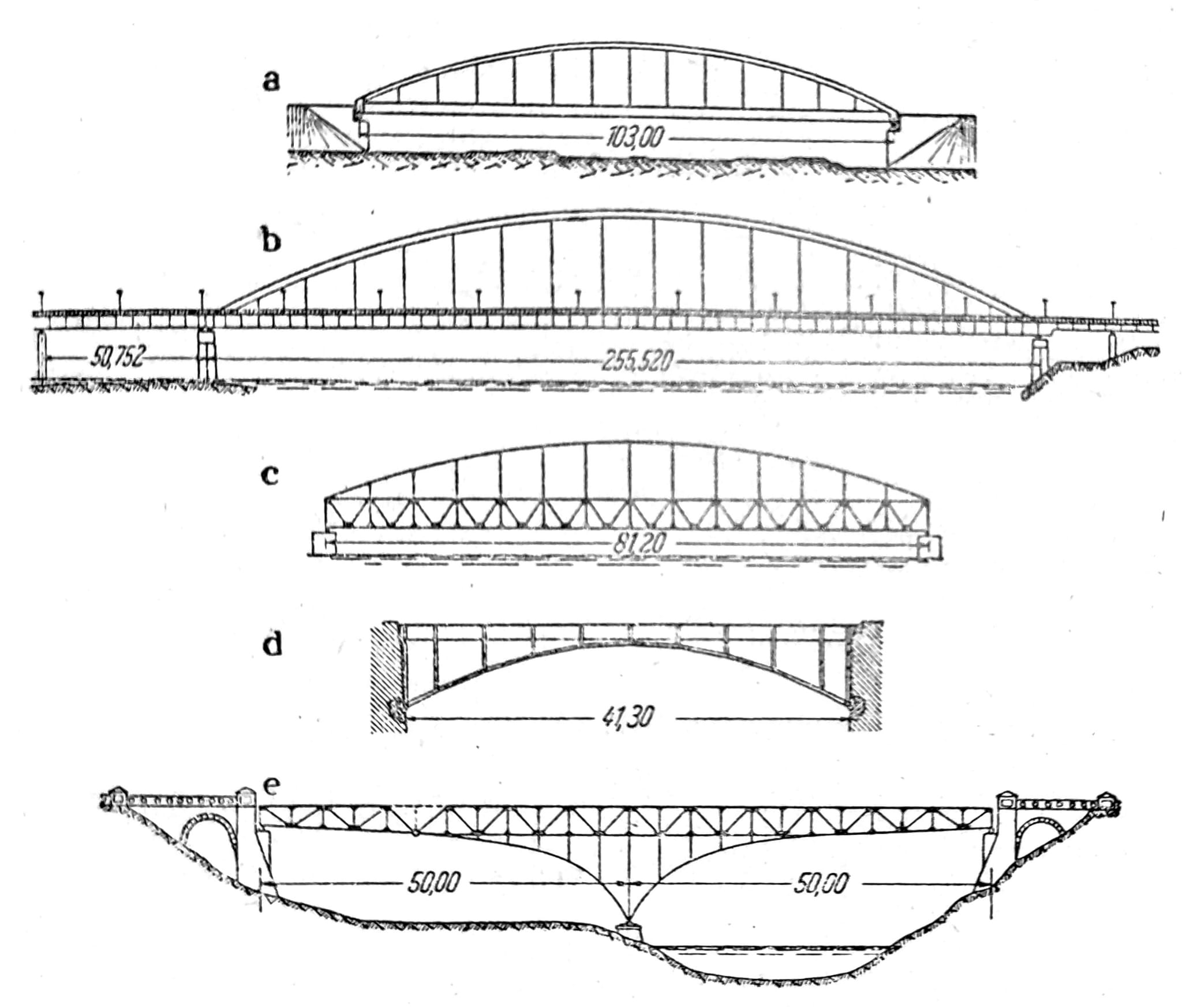
א) קונסטרוקציות קשתות. Clamped harbors are rarely built due to the difficulties in support clamping. הנפוצים ביותר הם יציאות על שני מפרקים. Ports with three hinges have the advantage that the movement of the supports and the change in temperature do not cause forces in them. They are particularly applicable for low ratio f/l and for the case of unreliable soil. Rigid ports are made as grids (fig. 1) or as metal supports (fig. 2). The arched structure is located above and below the roadway, sunken roadway is avoided for aesthetic reasons. Ports above the roadway receive braces in order to receive the thrust of the port. If the arch is rigidly connected to the beams of the adjacent openings (fig. 1 c and e), the static dimensions can be influenced within wide limits.
b) Langer beams have relatively strong arches, since the bending length is equal to the distance between the nodes of the upper connection. פתרונות עם קשת מתחת למדרכה (איור 3d) משמשים לעתים רחוקות בגשרים. הקורה עבור קשיחים יכולה להיות מתכת מתכת או רשת. With both solutions, that beam can be continuously continued into neighboring fields, so that continuous or Gerber systems are created (fig. 3b). באיור. 4 מציג חתך של גשר עם קורה אמצעית אחת. The supporting structure consists of a rod arch, rigid hangers and a closed hollow box as a stiffening beam that receives torsion and bending moments.
איור. 3 — קורות לנגר

איור. 4 — חתך של גשר עם קורת ביניים ראשית אחת
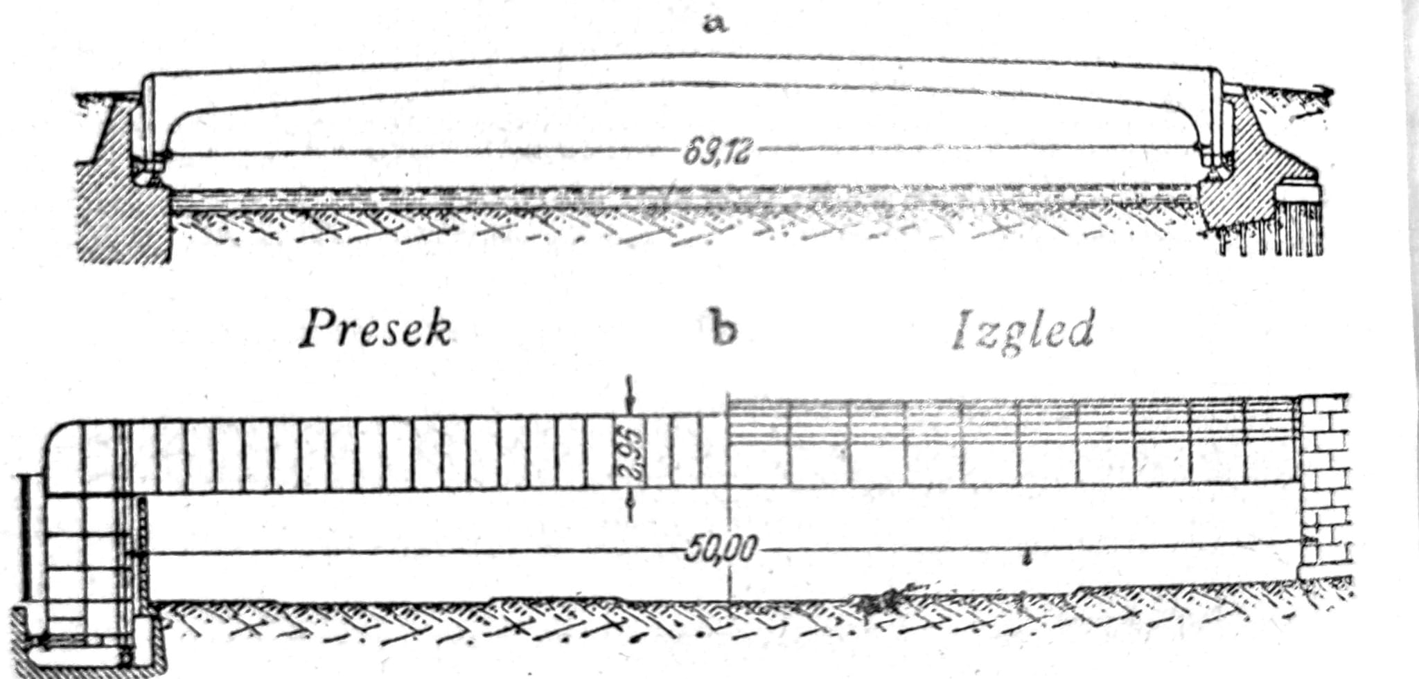
c) Frame bridges. When it is necessary to ensure the free height of the profile over the entire width of the opening, frames are applied on two or three joints with a lower support height than with simple beams due to the action of the frame (fig. 5).
e) חישוב. קשתות מחושבות בדרך כלל בהנחה שהציר שלהן אינו מתעוות. עם זאת, עיוותים אלסטיים יכולים להיות ניכרים. In solutions with suspended tension, the static values do not change much due to deformation, while the deformation of straight arches and Langer beams can have a significant effect on the static values.
איור. 5 — גשרי מסגרת
גשרים תלויים
גשרים תלויים סריג, שהם קשיחים בפני עצמם, נבנו לעתים רחוקות מאוד. לגשרים תלויים מודרניים יש קרן מקשיחה, המגבילה ומשווה כיפוף מכוחות מרוכזים. Suspension bridges with large spans are the Golden Gate Bridge near San Francisco (Fig. 6a) span 1280m, and the Washington Bridge near New York (Fig. 6b) span 1067m.
קורות קשיחות הן מתכת או סריג, בגובה קבוע או עם עלייה קטנה בגובה מעל התומכים האמצעיים. היחס בין בום לטווח נבחר בעיקר ביחס 1/9 ל-1/11. Various accidents have shown that at low heights, the stiffness can be too low, especially with a low own weight and a small width of the bridge.
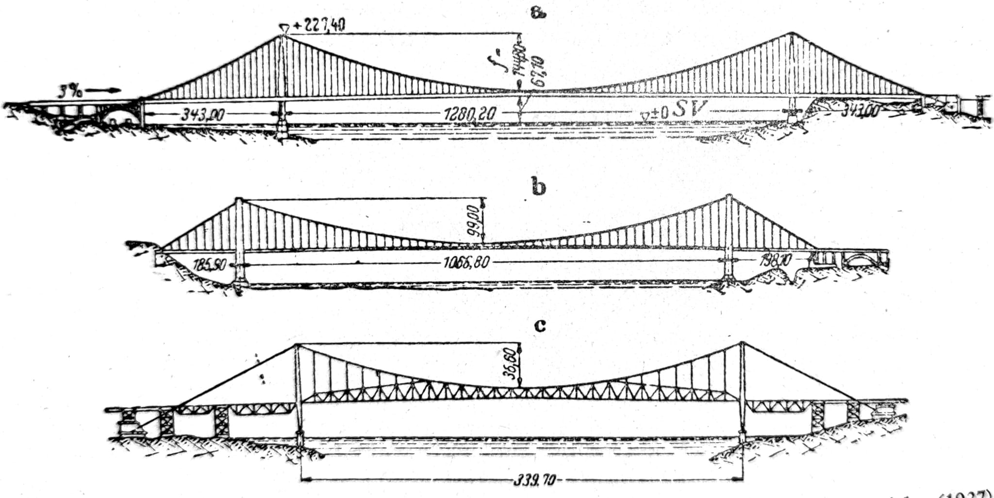
איור. 6 — American suspension bridges: a) Golden Gate Bridge in San Francisco (1937), b) Washington Bridge in New York (1931), c) Florianopolis Bridge in Brasilia (1926)
Sprocket
a) Articulated chains of links with expanded ends, which lie freely parallel to each other and face each other at the joints with overlapping links from adjacent fields, are made in two ways - with nailed reinforcements from lamellae at the ends or with expanded ends obtained by forging (fig. 7). שרשרת הגשר על פני הריין נבנתה מפלדת ניקל בעלת חוזק מתיחה של 5,5 עד 6,5 t/cm2. בגשרים תלויים אמריקאים קטנים יותר, השרשרת עשויה מפלדה יצוקה רגילה, בחלק מהמקרים גם מסגסוגת או פלדה מוקשה.
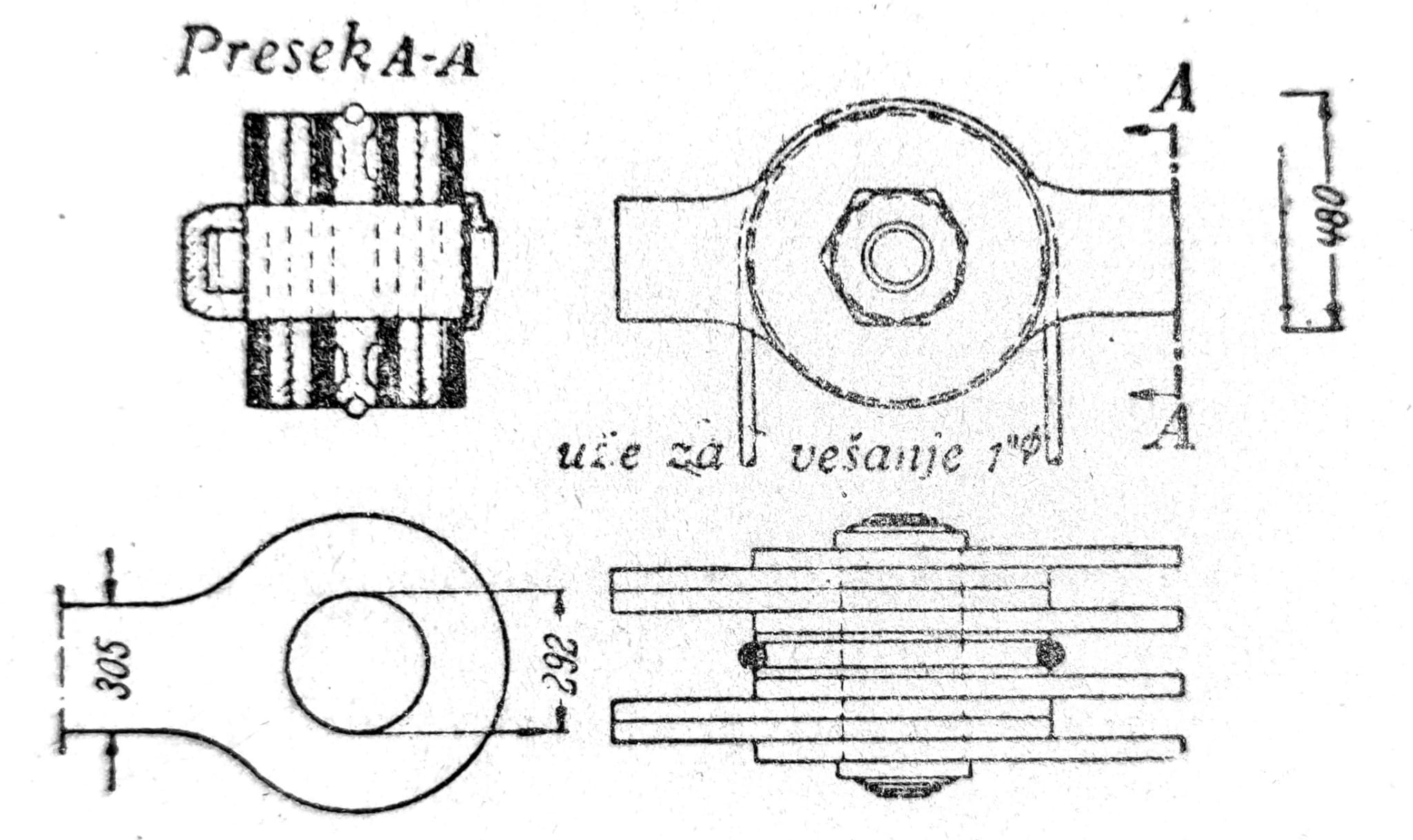
איור. 7 — שרשרת גשר פלוריאנופוליס
b) כבלי חבל ספירלי. חבלים סגורים עשויים מחוט בהיר. The inner layers of the wire are protected with a coating of lead minium, while the outer surfaces of individual wires are coated with a protective layer.
Spiral round wire ropes in American bridges consist mostly of wires that are hot-dip galvanized and partially wrapped in a similar manner.
חוטי גשר נמשכים בקור הם בעלי חוזק שבירה מ-12 ל-20 t/cm2. חוזק העייפות יכול להיות מופחת באופן משמעותי אם המשטח החיצוני של החוטים הקרים במצב גרוע.
התארכות החבל הספירלי תלויה בחומר לחוטים וכן בשיטת הכנת החבל. התפשטות אלסטית באזור הלחצים המותרים הרגילים מסתכמת ב-0,003 עד 0,004. Since the ropes are permanently, plastically stretched by 0,001 during the first load, sometimes before use the ropes are pre-loaded with the greatest force and thus stretched. The benefit of this stretch is limited, as a significant portion of the “permanent stretch” is lost after loosening the rope during further installation.
Historical units, steel names, protective coatings, strengths, expansions and methods of making or pouring cable heads are not modern specifications. מצבם של שרשראות, חבלים, עוגנים, ראשי כבלים וציפוי מגן קיימים, נקבע על ידי תיעוד, בדיקה ובדיקה; לא ניתן להסיק מטקסט כללי זה.
עיגון
שרשרות של קרסוליים מעוגנות באמצעות תקעים בתומכים שמוטבעים ביסודות לעיגון.
לחבלים ספירליים יש ראשים תואמים בקצוות (איור 8). שבו החוטים מתפרקים בצורת מטאטא, ולאחר הניקוי ממלאים אותם במתכת לבנה. לראשים יצוקים במומחיות יש את אותו חוזק כמו חבל.

איור. 8 — ראשי כבלים: א) ראש פשוט, ב) ראש אמריקאי, ג) ראש גשר הריין
מתלים וקשרי כבלים
המתלים עשויים מפלדה עגולה, במיוחד מצינורות או חבלי תיל (איור 9 ו-11). במקרה של חבלים סגורים, חבלי הכבלים מכוסים בקשרי כבלים (איור 10). In the case of separate cable bundles, the suspensions are designed in such a way that individual ropes can be replaced with new ones if necessary. מתלי החבל קשורים עם ראשי כבלים, בעוד שהפרשי אורך קטנים מתואמים עם שיבולים.

איור. 9 — תלוי, גשר ישן מעל הריין
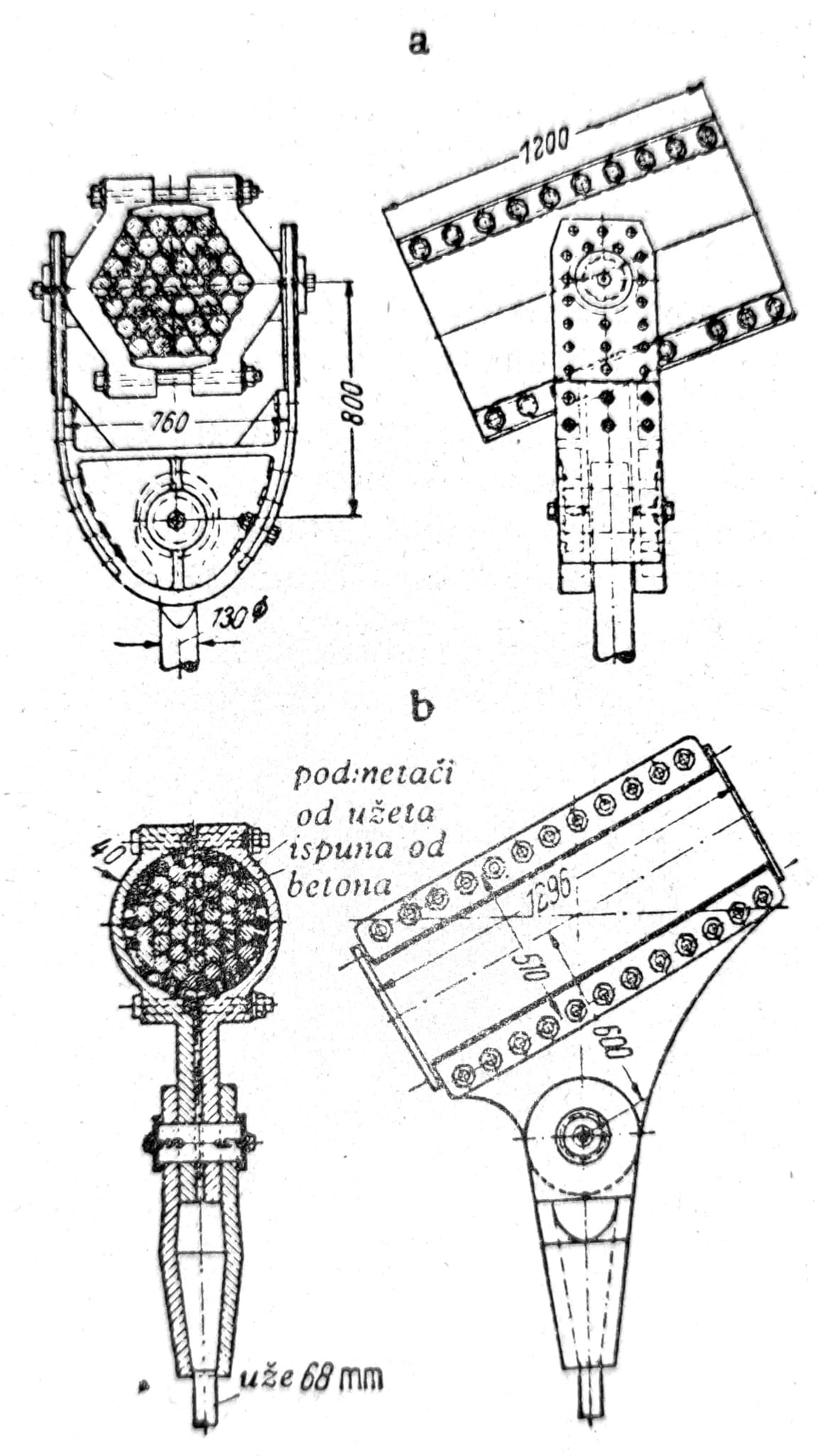
איור. 10 — קשרי כבלים של הגשר מעל הריין: א) גשר חדש, ב) גשר ישן

איור. 11 — חבלים לקשירת כבלים ומתלה
מגדלים (עמודים)
המגדלים של גשרים תלויים תלויים בתחתית, או שניתן להדק אותם, מה שקורה בעיקר באמריקה. השרשרת מחוברת היטב למגדלים. Movable support is necessary only when the towers cannot be entrusted with horizontal forces, which would occur with stationary supports.
לגשרים תלויים גדולים, עדיפים מגדלים תלושים נמוכים יותר. במקרה זה, ניתן להרכיב תחילה את המגדלים, לאחר מכן את השרשרת והמתלים, ולבסוף את קורות ההקשחה. In self-anchored suspension bridges, extensive scaffolding is required as the static system only begins to act when the stiffening beam is closed.
תומכי כביש ולוח כביש
In view of traffic and maintenance, we should try to ensure that the pavement on the bridge does not differ, if possible, from the pavement on the connecting parts of the road or railway. Since the pavement itself does not have enough stiffness of its own, it must rely on a surface system in the vertical direction, as well as on a system that provides it with horizontal lateral support. מה שנקרא לוח מסלול נשען על תומכי מסלול, המורכבים בעיקר מתומכים אורכיים ורוחביים.
רוחבי תומך
קורות רוחביות מעבירות עומסים נעים אל הקורות הראשיות. הם גם חלק חשוב בחיבורים. Transverse girders lie directly on the main girders and in case of inclined bridges, so their span is equal to the spacing of the main girders. תומכים רוחביים הם בדרך כלל מתכת, עבור אורכים קצרים ותומכים מגולגלים רגילים. It is useful that their height is in the 1/6 to 1/8 range, although in the case of large bridges and the small distance between the transverse supports (especially in the case of pavement boards), this height can be even 1/20 טווח.
As a rule, transverse girders are considered as simple beams, which are rigidly connected to the main girders, so that in the cross section of the bridge open or closed frames are formed. בגלל זה, מתרחשים רגעי צביטה, שיש לקחת בחשבון במיוחד עם חיבורים.
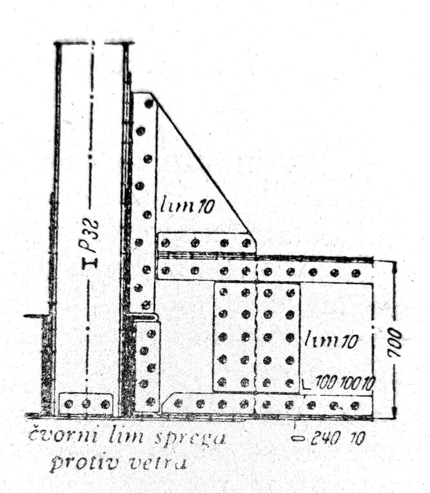
איור. 12 — חיבור מוט צולב
במקרה שהריצוף מתחת, החיבור נעשה בזוויות חיבור פשוטות, או. road plates, which are inserted into the cross member (fig. 12), or in the verticals of the I-section, and in place of their ribs (fig. 13). הפתרון באיור. 14 is particularly rigid, since there the cantilever sheet is embedded both in the transverse support and in the vertical, so that the moment at the corner is received by the shear bolts. עם פתרונות אחרים, לא ניתן להימנע מכך שהברגים נקרעים חלקית ושזוויות החיבור מכופפות. חיבורים לפי איור. 12 ו-13 מעוותים באופן משמעותי יותר בהשפעת הרגע מאשר אלו שלפי איור. 14. פתרונות דומים עולים עבור עמדות מדרכה אחרות. Laying of transverse supports on the main supports is possible only with sufficient structural height. לאחר מכן יש להקשיח את תומכי הפח הראשיים במקומות שבהם פועל העומס.

איור. 13 ו-14 — גרסאות של חיבור קורות צולבות
תמיכות אורכיות
תומכים אורכיים יכולים להיות מתחת לכביש ומתחת למעברים להולכי רגל. הקורה החיצונית, המחוברת לעתים קרובות למעקה הגשר, נקראת קורת הקצה האורך. תומכים אורכיים עשויים מתומכי מתכת מגולגלים ופח. הטווח שלהם הוא עד 12 m. Since the longitudinal beams are exposed to the most direct influence of the moving load, their rigidity against bending is particularly important. עבור גשרי רכבת, מכוון גובה הקורה של 1/8 עד 1/10. תומכים אורכיים העשויים מפלדה איכותית בדרך כלל אינם מתאימים עקב כיפוף גבוה. בגשרים ישנים רבים בוצע חיבור הקורות האורכיות לפי איור. 15. זווית חיבור אחת מונחת בין רגלי התומך המגולגל, ואילו השנייה מונחת על כל גובה התומך הצלב. With these types of connections, significant secondary stresses occur, and in many cases, fatigue breaks have occurred with them, as well as cracks at the point where the leg is cut. מסיבה זו, חיבורים כאלה אינם מותרים בגשרי רכבת. אם לא ניתן להימנע מחיתוך הרגליים, יש לבצע חיתוכים אלו עם עיגול גדול, על מנת למנוע סכנת סדקים.
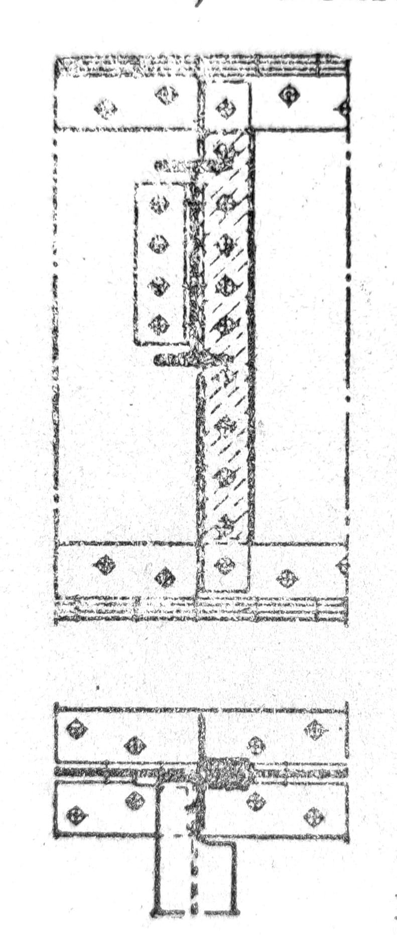
איור. 15 — חיבור תמיכה אורכי
ניקוז
Drainage of bridges should be given great attention. Quick and complete drainage of water is the most important prerequisite for the long life of the road surface, as well as the bridge itself. In addition to increased rusting and increased maintenance costs, water retention areas are also dangerous due to frost damage. If the level of the bridge allows it, road bridges should have a certain longitudinal drop (not less than 1%), which would ensure the flow of water to the drain. Water contaminated with oil and dust is drained away through gutters. These gutters must have a sufficient longitudinal fall and must be accessible, in order to be cleaned regularly.
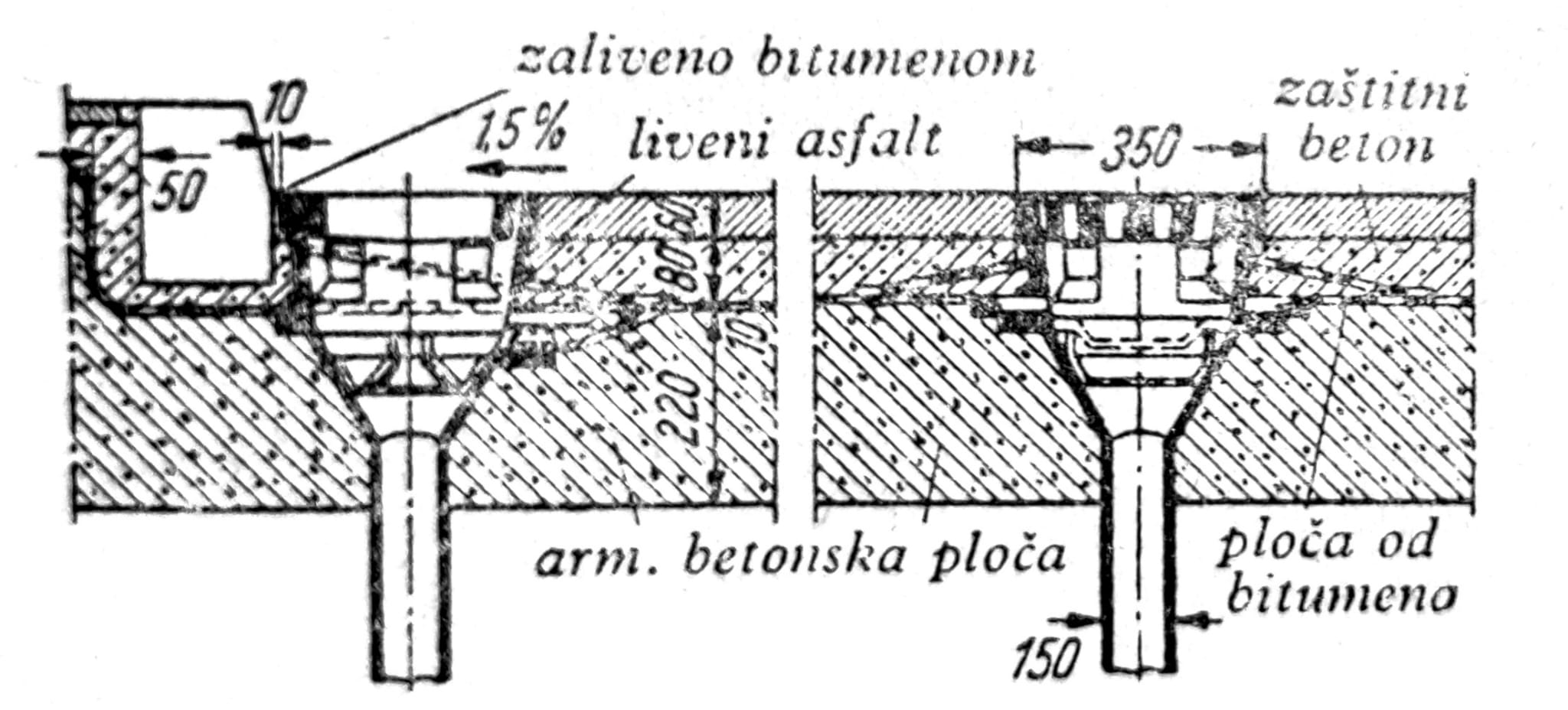
איור. 16 — Drainage and protective layers of road surface
Asphalt pavements are not absolutely impermeable. Special insulation under the asphalt can be dispensed with if the asphalt lies on a concrete slab that has been vibrated, and that slab itself is largely impermeable. If the pavement is not sufficiently impermeable, so that a part of the storm water penetrates, insulation should be provided. For steel bridges, coatings of asphalt bitumen or terra etc., insulating layers of bituminous insulating masses with solid inserts of paper with wool felt or jute weaving, as well as insulating layers of metal foils of copper or aluminum are considered. Insulation layers must be protected from mechanical damage with protective layers.
Descriptions of falls, gutters, asphalt, concrete slabs, bituminous masses, felt, jute and metal foils are historical. Modern drainage, waterproofing, steel protection, penetration details and maintenance are designed as a harmonized system according to current regulations, climatic conditions, traffic and actual construction.
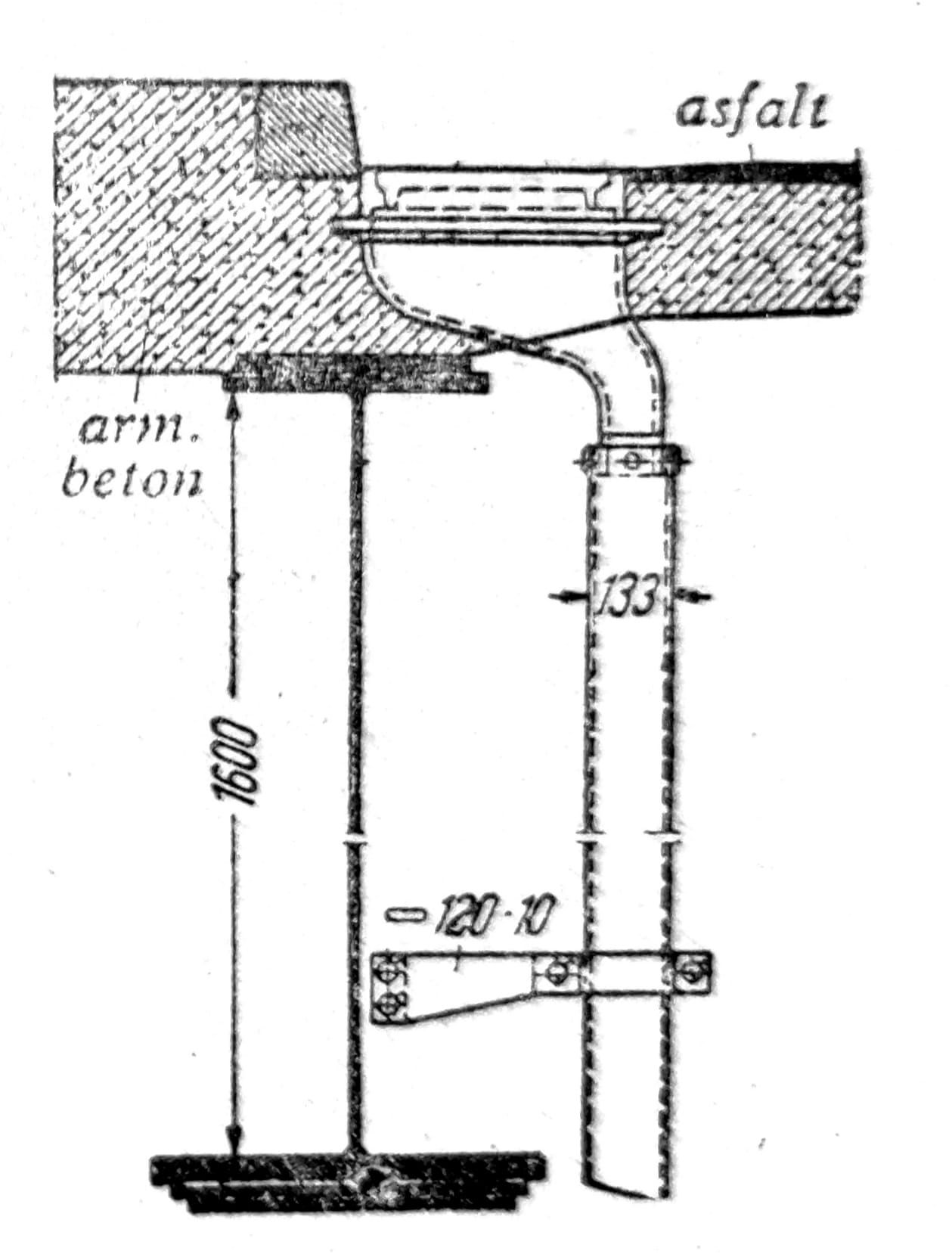
Fig. 17 — Detail of drainage along the edge of the bridge
צימודים
Tin supports have little stiffness in the direction perpendicular to the plane of the support, grids with assumed joints in the nodes are even multiple movable in the transverse direction. Therefore, wind braces and cross frames are needed to create spatially stable structures first. Furthermore, they should receive loads that act transversely to the plane of the main supports, and finally ensure the construction against buckling and overturning.
Couplings against the wind
These couplings are dimensioned to receive forces from wind and other horizontal loads. They consist of grids or frame supports, straight or curved according to the belts. Belts of couplings against the wind are mostly also belts of the main supports. Often the transverse supports are also the verticals of the coupling against the wind.
For a loaded bridge, less wind load is taken than for an unloaded bridge. If the cross-section allows it, truss bridges preferably have two wind braces between the girders of the main girders. ראה סקיצות מערכת באיור. 18 in which anti-wind couplings and transverse couplings are marked with dashed lines.
The number and type of transverse couplings must be sufficient to create a spatially rigid system. It is common for grids to ensure stability in the case of ball joints as well. Ports and Gerber beams, with the exception of small bridges, are stiffened with special couplings against wind and against buckling. At the joints of the main supports, the couplings must be made in such a way that they do not affect the action of the joints, fig. 18e.
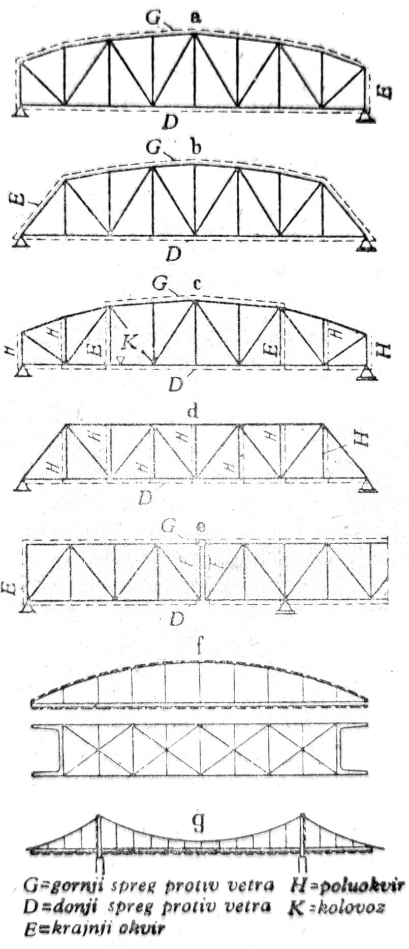
Fig. 18 — Layout of couplings against wind
Wide pavement boards made of sheet metal or reinforced concrete are very rigid in their planes. If the spans are not too large, special couplings against the wind can be omitted, since the appropriate role can be taken by the pavement board. Measures must be taken to receive transverse forces only during assembly.
When choosing the filling, it should be borne in mind that generally the forces in the rods are small and the bending lengths of the rods are large. Therefore lattices with short rod lengths (eg K-system or rhombic system) are preferred. Sometimes, the anti-wind coupling is hung on the road supports in order to reduce the bending length. For couplings above the pavement, the rhombic system without verticals is often used.
The height position of the coupling against the wind is determined mainly by structural conditions (fig. 19). If possible, an eccentric connection is avoided here as well. especially with high forces, and the coupling against the wind is set so that the shafts of the rods intersect in the planes of the main supports (fig. 20).

איור. 19 — Altitude position of anti-wind coupling

איור. 20 — Antiwind Coupling Node
מסגרות צולבות
Bridges with roadway above can be stiffened with light lattice frames according to fig. 22. Transverse couplings in the form of a frame can be connected to the main stiffeners of sheet metal beams. באיור. 21 many cables are placed over the tension frame on two joints, i.e. over the grill under the cross member, so that they are accessible from the middle inspection track.
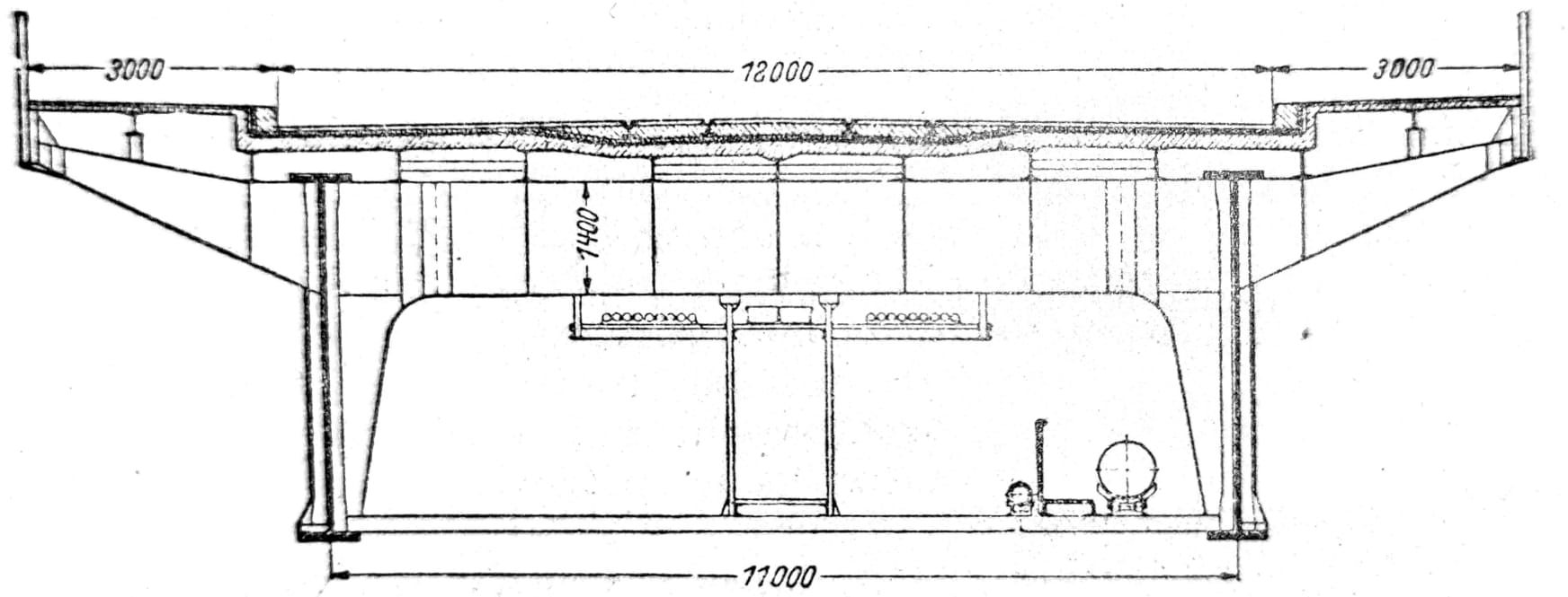
Fig. 21 — Transverse frame and installation guide

Fig. 22 — Lattice cross frame
For bridges with a roadway below, the shape of the transverse frames is determined by the free profile for the passage of vehicles. Bridges with lattice transverse frames are shown in fig. 23d. Transverse frames that distribute the load (fig. 24) are needed for grills in order to engage the cooperation of all the main supports even for a partial load. If it is a railway bridge with a curved track or if the main girders are in a curve, this should be taken into account during the static calculation of couplings.
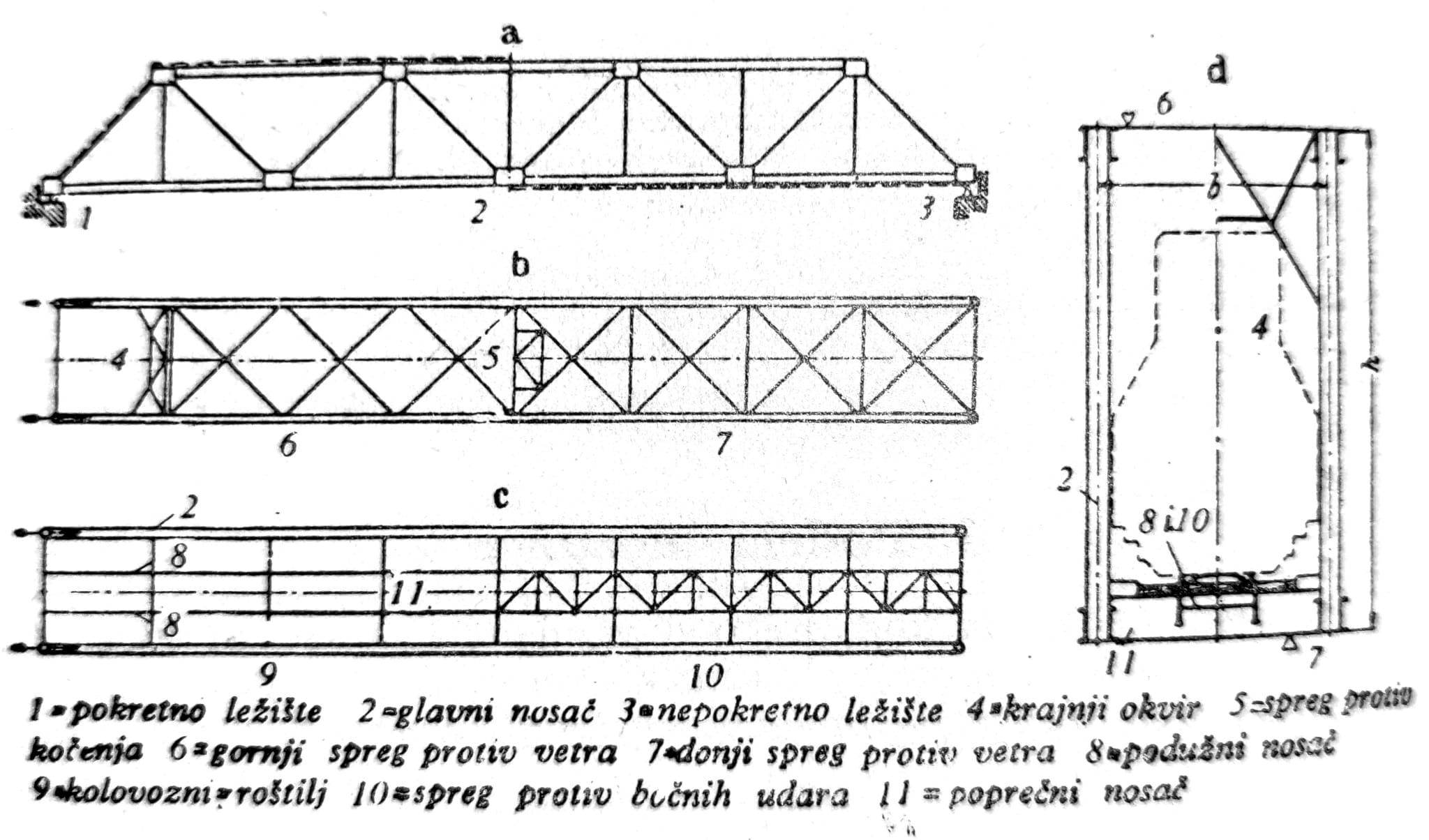
Fig. 23 — Examples of transverse couplings and main supports
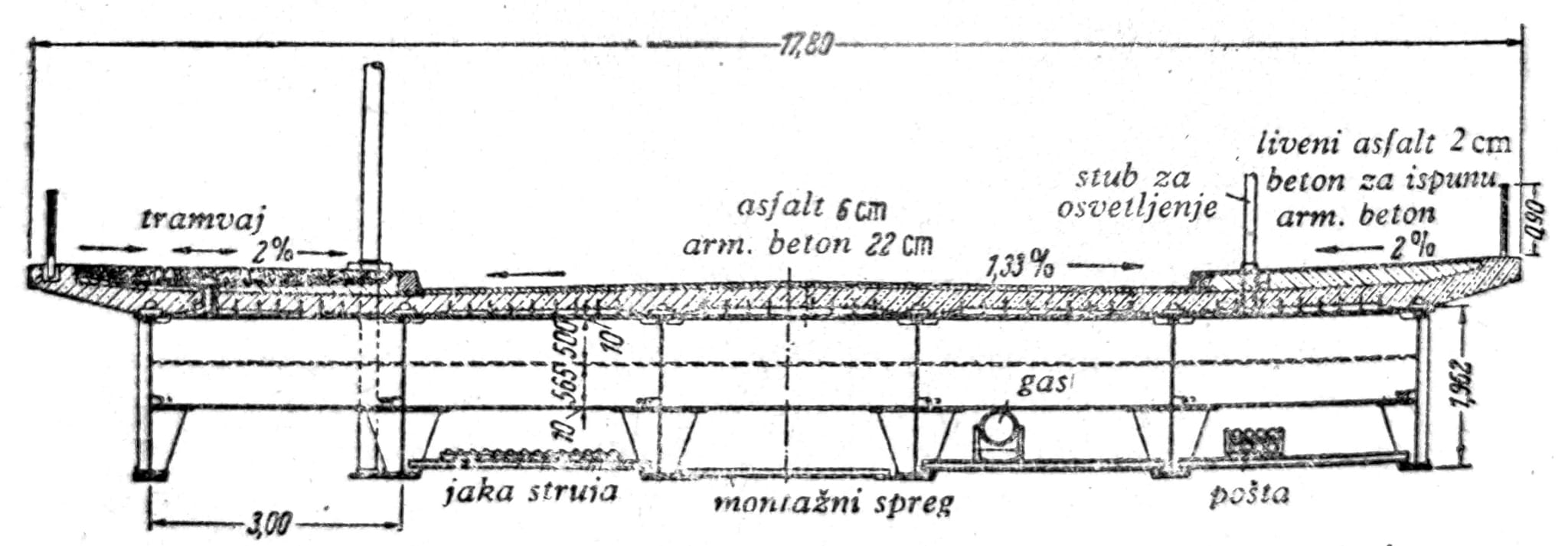
Fig. 24 — Cross section and cross beam for load distribution on the bridge over the Ruhr River near Herdecke
צימוד פגיעות צד
Between the longitudinal supports of railway bridges (fig. 23c) it is necessary to provide a special coupling for the reception of side impacts of vehicles. Longitudinal I-girders are proportionally very little rigid in the transverse direction, so it is desirable that the coupling against lateral impacts increases their safety against lateral buckling (Fig. 25).
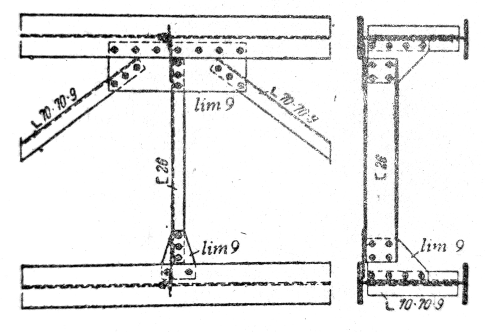
איור. 25 — צימוד נגד פגיעות צד
מצמד נגד בלימה
Transverse girders are not able to receive the forces that act in the longitudinal direction of the bridge and occur when braking or starting to drive the vehicle, and they should be relieved by installing anti-braking couplings. הם תומכים שטוחים סריג (איור 26) המחברים את התומכים האורך עם צימוד נגד הרוח (איור 27). לעתים קרובות יש הבדל גובה בין המנשא לצימוד. And in cases where the length of the supports can be directly connected with the anti-wind coupling, a special anti-braking coupling is needed, since the rods filling the anti-wind coupling are not able to receive a significant bending load. במקרים מסוימים, ניתן לשלב אותו לכדי צימוד כביש אחד נגד רוח, צימוד נגד פגיעות צד וצימוד נגד בלימה.
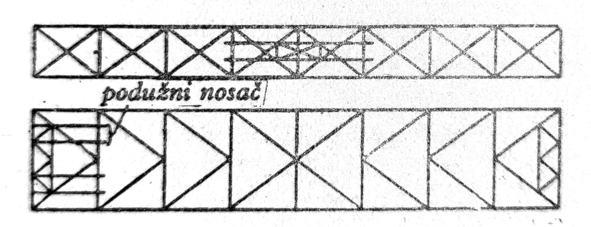
איור. 26 — מערכת מצמד נגד בלימה

איור. 27 — מצמד נגד בלימה