Important professional and safety note: This is an archival professional review, not a design, static calculation, assessment of an existing bridge, or instructions for construction, inspection or rehabilitation. The original divisions, spans, ratios, stresses, materials, joint details and construction solutions have been transferred without professional verification and should not be used as a modern specification. Designing and works on bridges require authorized designers and contractors, current regulations and standards, geotechnical and hydrological data, calculation of permanent and variable effects, fatigue, wind, temperature, seismicity, stability, foundations, assembly conditions and robustness, as well as testing of materials, corrosion, joints and the actual condition of the structure. Access to the structure, working at height, traffic, lifting, welding, cutting and assembly carry deadly risks and require a special protection plan.
The design, construction and rehabilitation of steel bridges are not part of the new public offer of the company Savo Kusić. Current focus is wood windows, wood-aluminum windows, custom windows and doors. For a window or door project, you can send request for quote.
Arch bridges
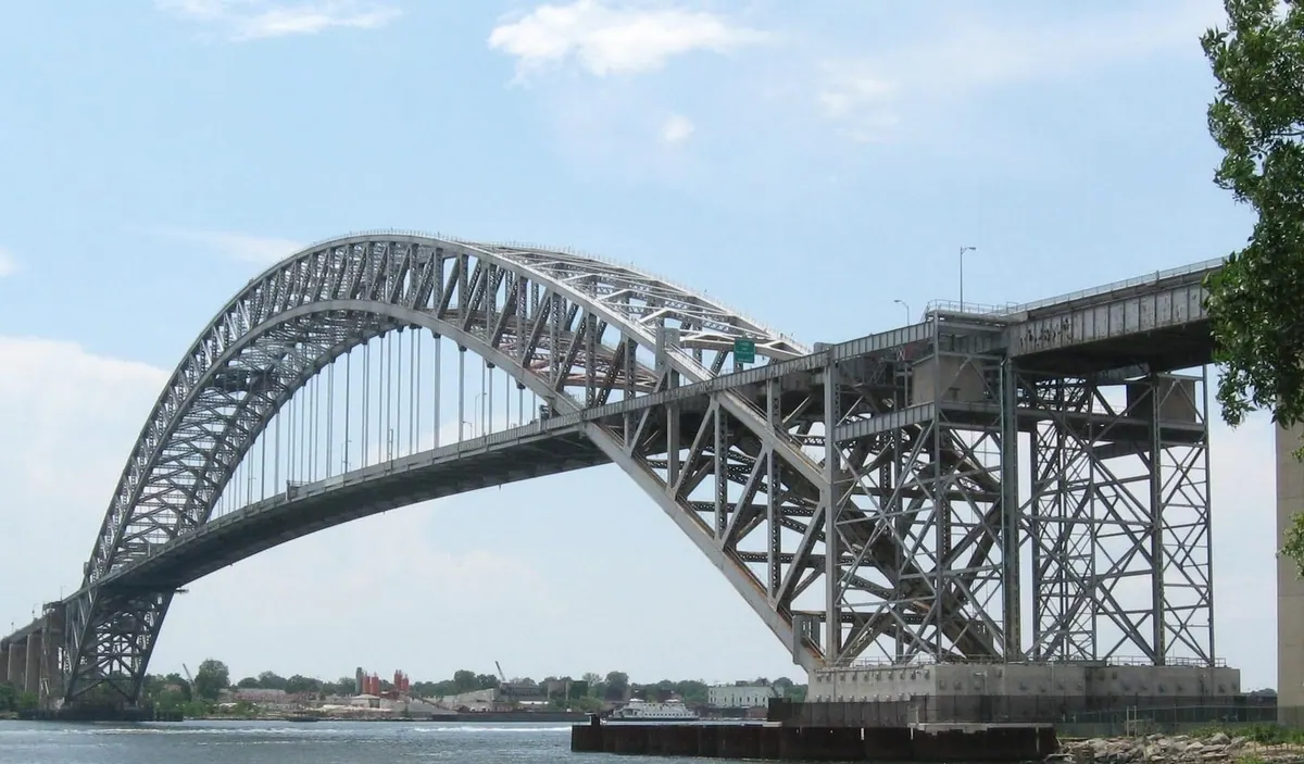
There are real arch bridges with rigid arches, which can take all kinds of impacts, and arch bridges composed of rods, where a rigid system is obtained by the existence of a stiffening beam. A stiffened arch (Langer beam) is calculated under the assumption of hinged connections, so the arch is loaded only with normal forces. Bending moments are taken over by the stiffening beam, which also performs the role of tension if the arch is located above the beam.
Arches and Langer beams are more economical than girder bridges for larger spans, because the equally distributed full load is received only by the supporting line of the arch. With the exception of additional forces, moments are caused by only partial loading, so they are significantly smaller in arches than in beams.

Fig. 1 — Lattice Ports

Fig. 2 — Tin ports
a) Arch constructions. Clamped harbors are rarely built due to the difficulties in support clamping. The most common are ports on two joints. Ports with three hinges have the advantage that the movement of the supports and the change in temperature do not cause forces in them. They are particularly applicable for a small f/l ratio and for the case of unreliable soil. Rigid ports are made as grids (fig. 1) or as metal supports (fig. 2). The arched structure is located above and below the roadway, sunken roadway is avoided for aesthetic reasons. Ports above the roadway receive braces in order to receive the thrust of the port. If the arch is rigidly connected to the beams of the adjacent openings (fig. 1 c and e), the static parameters can be influenced within wide limits.
b) Langer beams have relatively strong arches, since the bending length is equal to the spacing of the nodes of the upper coupling. Solutions with an arch under the pavement (Fig. 3d) are rarely used in bridges. The beam for stiffeners can be sheet metal or grid. With both solutions, that beam can be continuously continued into neighboring fields, so that continuous or Gerber systems are created (fig. 3b). In fig. 4 shows a cross-section of a bridge with one middle girder. The load-bearing structure consists of a rod arch, rigid hangers and a closed hollow box as a stiffening beam that receives torsion and bending moments.
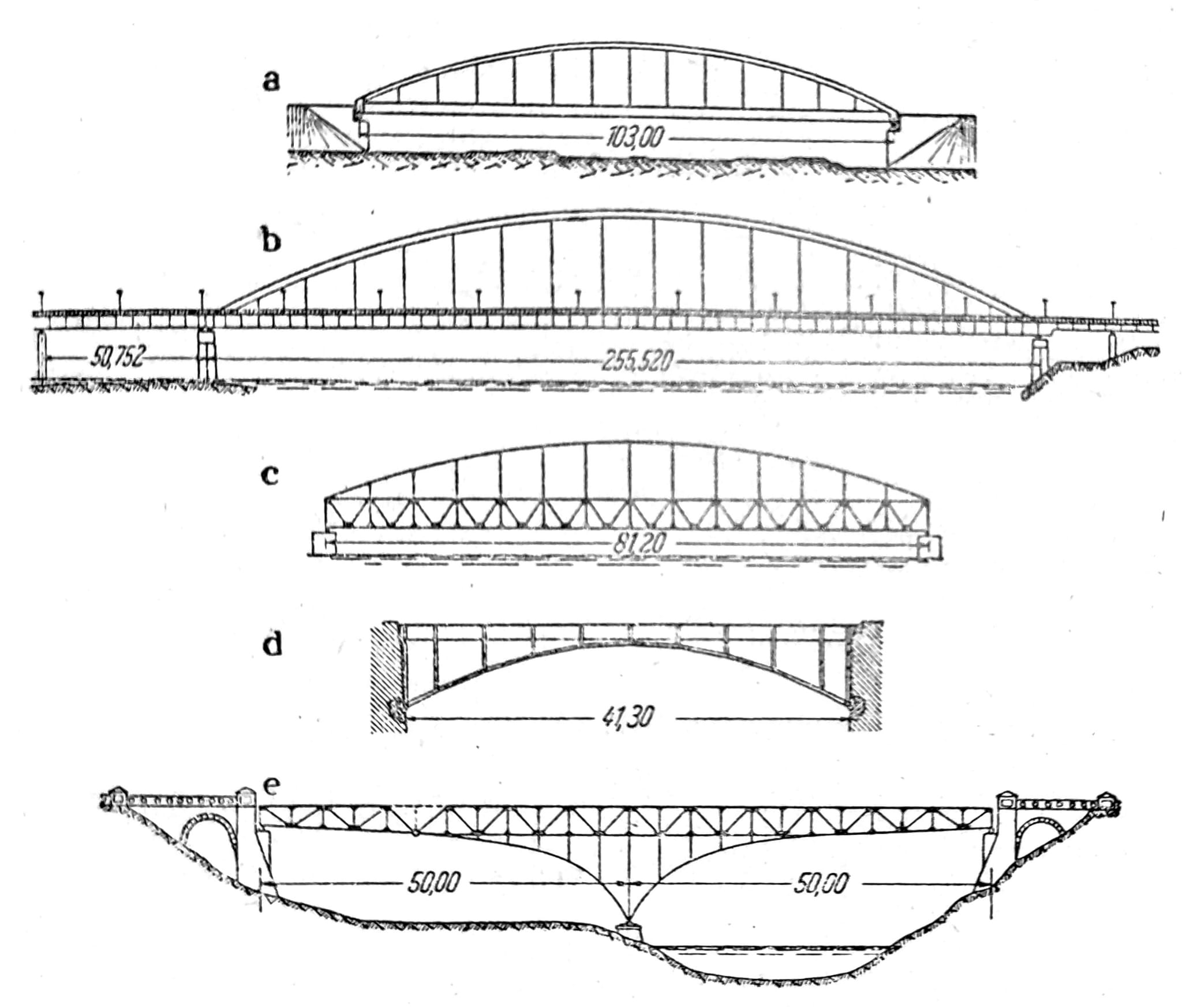
Fig. 3 — Langer beams

Fig. 4 — Cross-section of a bridge with one intermediate main girder
c) Frame bridges. When it is necessary to ensure the free height of the profile over the entire width of the opening, frames are applied on two or three joints with less support height than with simple beams due to the effect of the frame (fig. 5).
e) Calculation. Arches are usually calculated on the assumption that their axis does not deform. However, elastic deformations can be considerable. In suspended tension solutions, static quantities do not change much due to deformation, while deformation in straight arches and Langer beams can have a significant effect on static quantities.
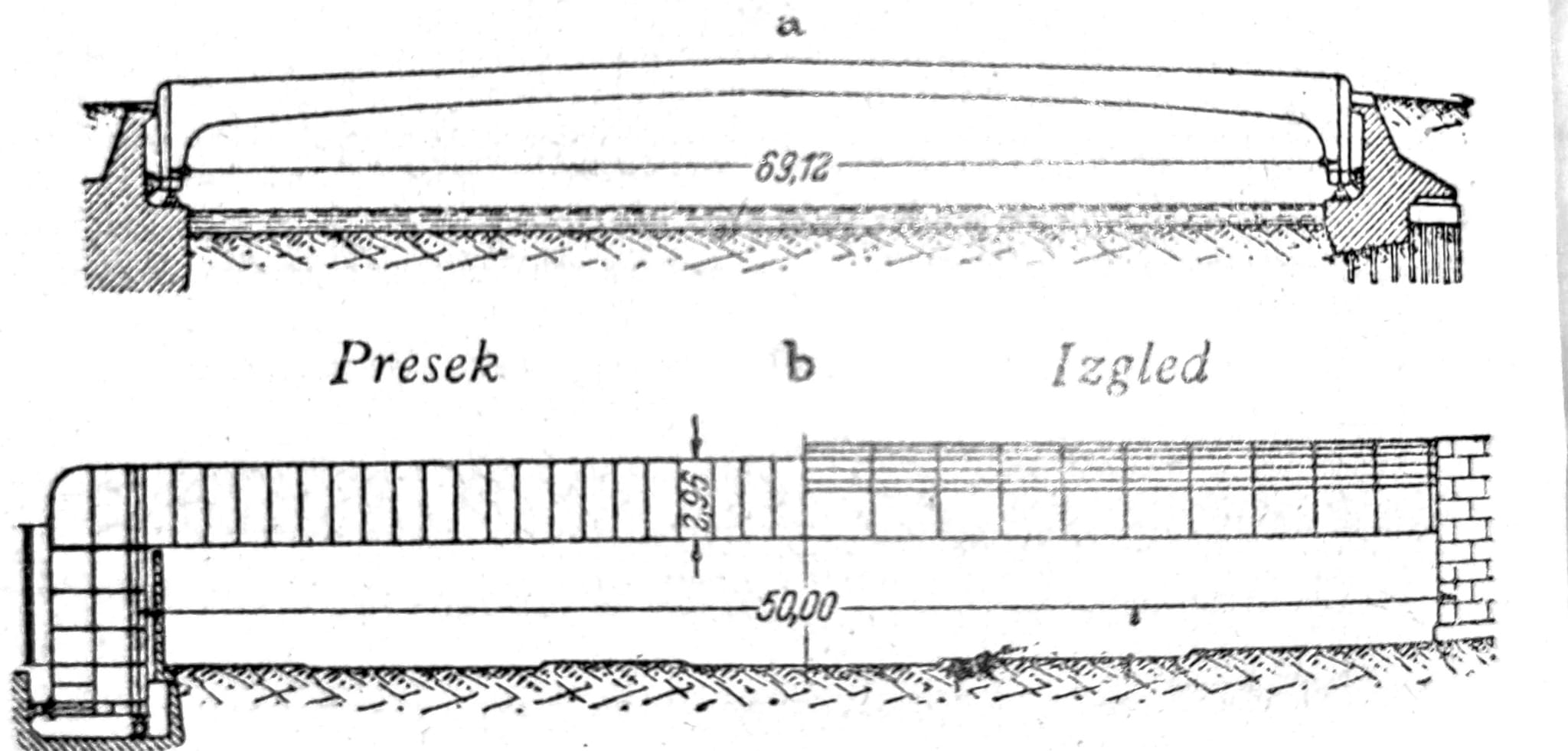
Fig. 5 — Frame bridges
Suspension bridges
Lattice suspension bridges, which are inherently rigid, are rarely built. Modern suspension bridges have a stiffening beam, which limits and equalizes bending from concentrated forces. Suspension bridges with large spans are the Golden Gate Bridge near San Francisco (fig. 6a) with a span of 1280m, and the Washington Bridge near New York (fig. 6b) with a span of 1067m.
Stiffening beams are sheet metal or lattice, of constant height or with a small increase in height above the middle supports. The boom-to-span ratio is usually chosen in the ratio 1/9 to 1/11. Various accidents have shown that at low heights, the stiffness can be too low, especially with low own weight and small width of the bridge.
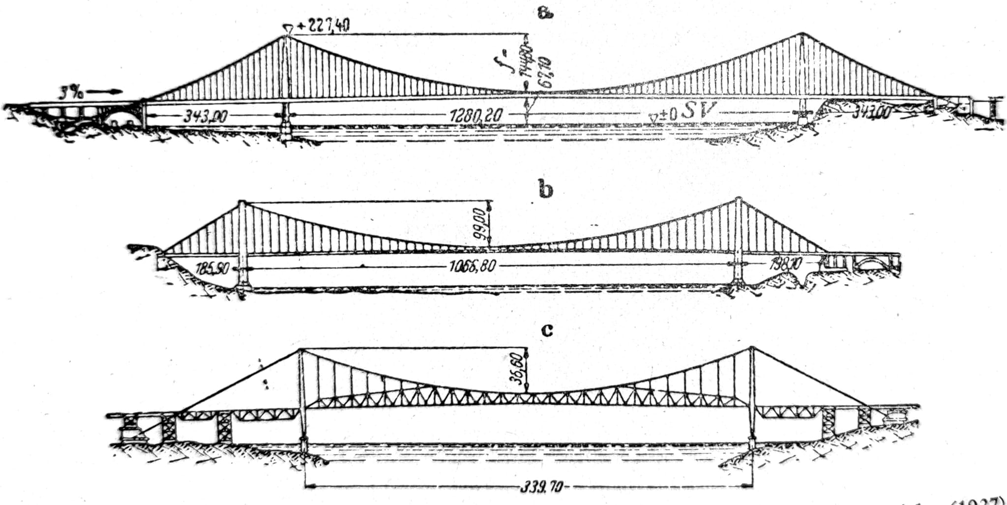
Fig. 6 — American suspension bridges: a) Golden Gate Bridge in San Francisco (1937), b) Washington Bridge in New York (1931), c) Florianopolis Bridge in Brasilia (1926)
Chain link
a) Articulated chains of links with expanded ends, which lie freely parallel to each other and face each other at the joints with overlapping links from adjacent fields, are made in two ways - with nailed reinforcements from lamellae at the ends or with expanded ends obtained by forging (fig. 7). The bridge chain across the Rhine was built from nickel steel with a tensile strength of 5,5 to 6,5 t/cm2. In smaller American suspension bridges, the chain is made from normal cast steel, and in some cases from alloy or hardened steel.
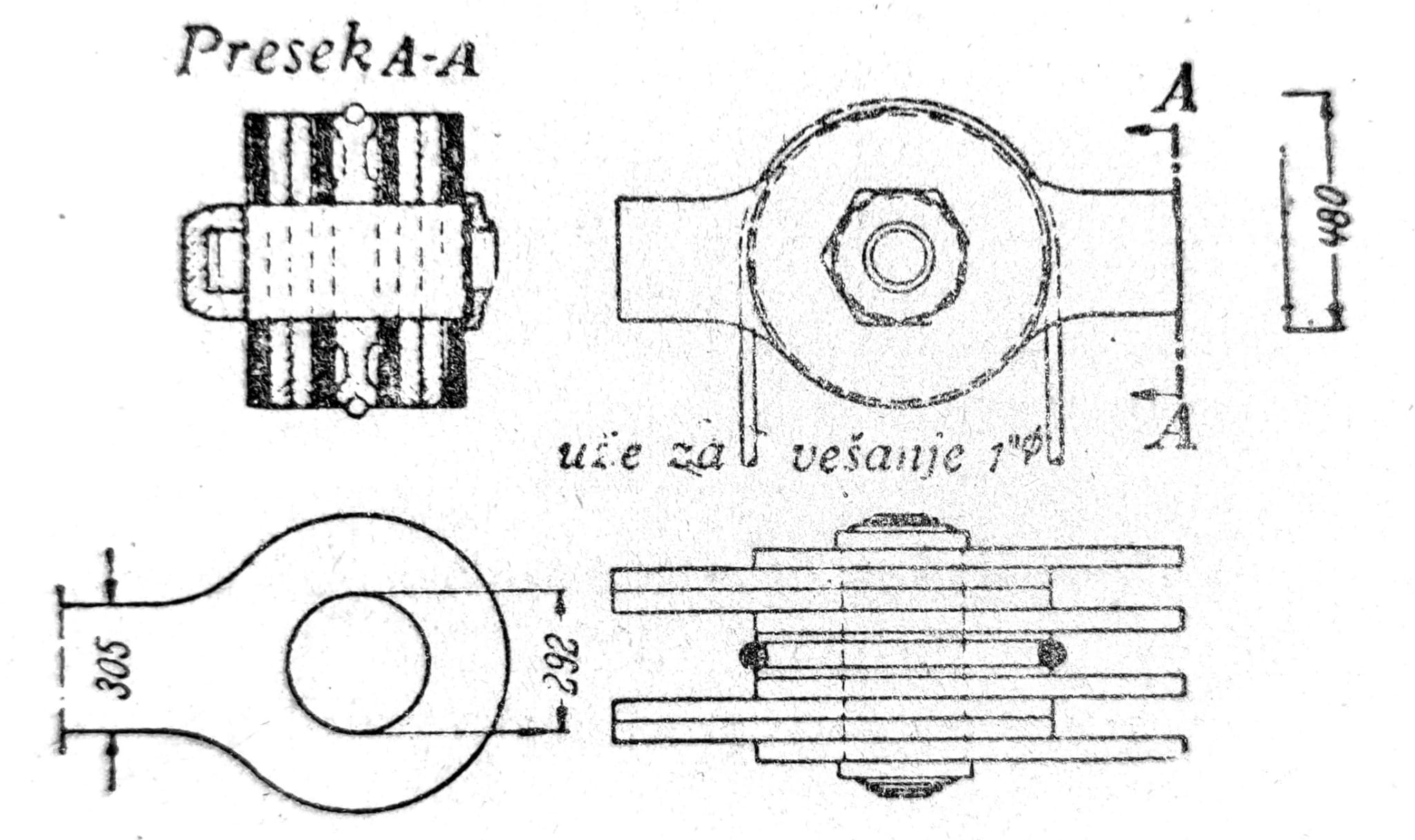
Fig. 7 — Florianopolis Bridge Chain
b) Spiral rope cables. Closed ropes are made of bright wire. The inner layers of the wire are protected with a coating of lead minium, while the outer surfaces of individual wires are coated with a protective layer.
The spiral cables of round wires in American bridges consist for the most part of wires which are hot-dip galvanized, and are partly wrapped in a similar manner.
Cold drawn bridge wires have a breaking strength of 12 to 20 t/cm2. Fatigue strength can be significantly reduced when the outer surface of cold drawn wires is in poor condition.
The elongation of the spiral rope depends on the material of the wires as well as the method of making the rope. Elastic expansion in the range of normal permissible stresses is 0,003 to 0,004. Since the ropes are permanently, plastically stretched by 0,001 during the first load, sometimes before use the ropes are pre-loaded with the greatest force and thus stretched. The benefit of this stretch is limited, as a significant portion of the “permanent stretch” is lost after loosening the rope during further installation.
Historical units, names of steel, protective coatings, strengths, expansions and methods of making or pouring cable heads are not modern specifications. The condition of existing chains, ropes, anchors, cable heads and protective coatings is determined by documentation, inspection and testing; cannot be deduced from this general text.
Anchoring
Chains made of articles are anchored using plugs in supports that are concreted into the foundations for anchoring.
Spiral ropes have corresponding heads at their ends (fig. 8). in which the wires are untangled in the shape of a broom, and after cleaning they are filled with white metal. Expertly cast heads have the same strength as the rope.

Fig. 8 — Cable heads: a) simple head, b) American head, c) Rhine bridge head
Suspension and cable ties
Hangers are made of round steel, especially of pipes or wire ropes (fig. 9 and 11). In the case of closed ropes, the cable ropes are covered with cable ties (fig. 10). In the case of separate cable bundles, the suspensions are designed in such a way that individual ropes can be replaced with new ones if necessary. Hangers made of ropes are tied with cable heads, while small differences in length are equalized with shims.

Fig. 9 — Suspension, old bridge over the Rhine
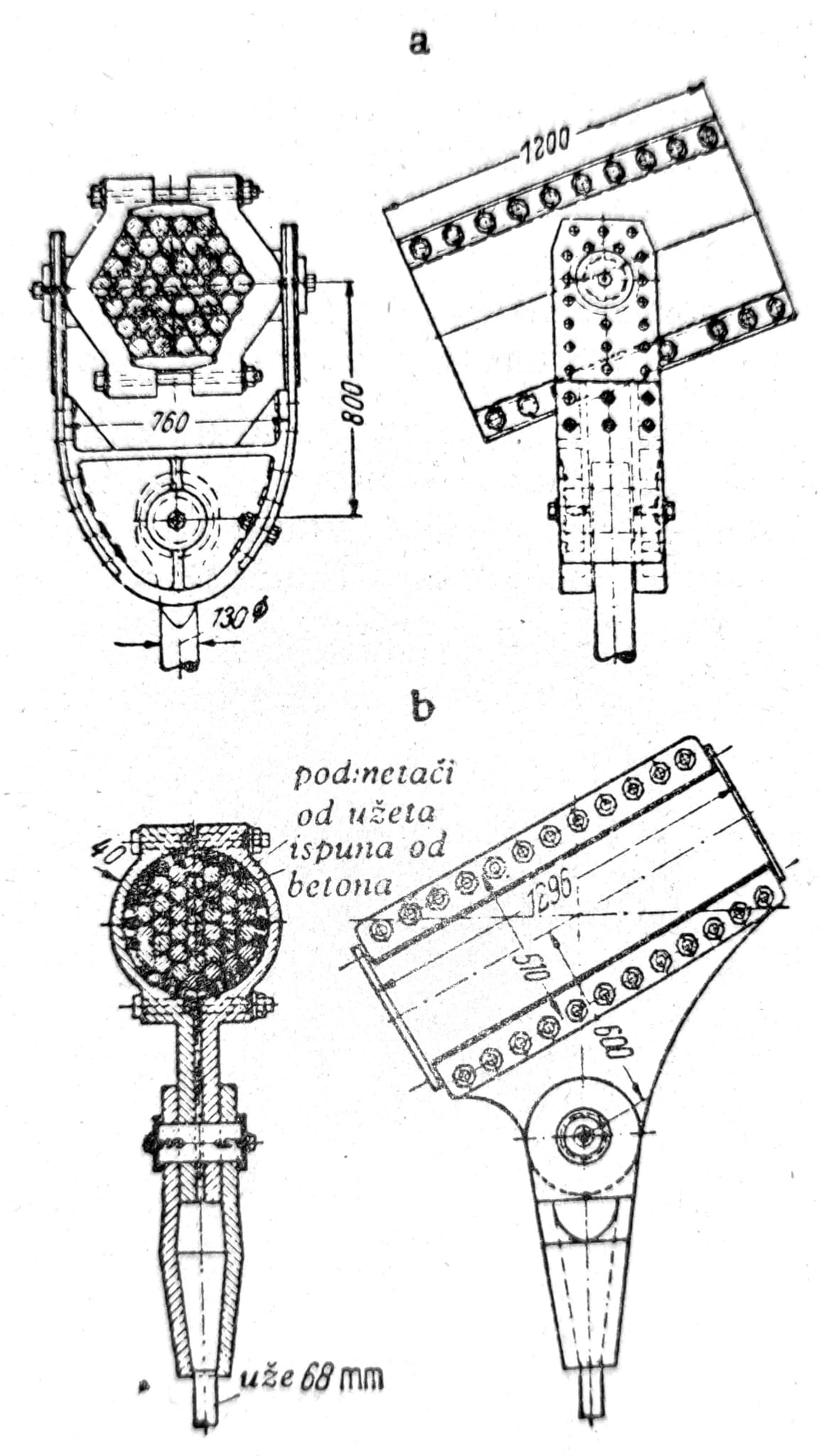
Fig. 10 — Cable ties of the bridge across the Rhine: a) new bridge, b) old bridge

Fig. 11 — Cable tie and hanger ropes
towers (pylons)
The towers of suspension bridges are hinged at the bottom, or they can be clamped, which is mostly the case in America. The chain is firmly attached to the towers. Movable support is necessary only when the towers cannot be entrusted with horizontal forces, which would occur with immobile supports.
For large suspension bridges, lower wedged towers are preferred. In that case, the towers can be mounted first, then the chainrings and hangers, and finally the stiffening beams. In self-anchored suspension bridges, extensive scaffolding is required since the static system only begins to act when the stiffening beam is closed.
Road supports and road board
With regard to traffic and maintenance, we should try to ensure that the pavement on the bridge does not differ, if possible, from the pavement on the connecting parts of the road or railway. Since the pavement itself does not have enough stiffness of its own, it must rely on a surface system in the vertical direction, as well as on a system that provides it with horizontal lateral support. The so-called track board rests on track girders, which mainly consist of longitudinal and transverse girders.
Transverse supports
Cross girders transfer the moving loads to the main girders. They are also an important part of couplings. Transverse girders lie directly on the main girders and in case of inclined bridges, so their span is equal to the spacing of the main girders. Transverse supports are usually sheet metal, for short lengths and ordinary rolled supports. It is useful that their height is 1/6 to 1/8 range, although in the case of large bridges and a small mutual distance of transverse girders (especially in the case of pavement boards), this height can be even 1/20 range.
As a rule, transverse supports are considered as simple beams, which are rigidly connected to the main supports, so that in the cross-section of the bridge open or closed frames are created. Because of this, pinching moments occur, which should be taken into account especially with connections.
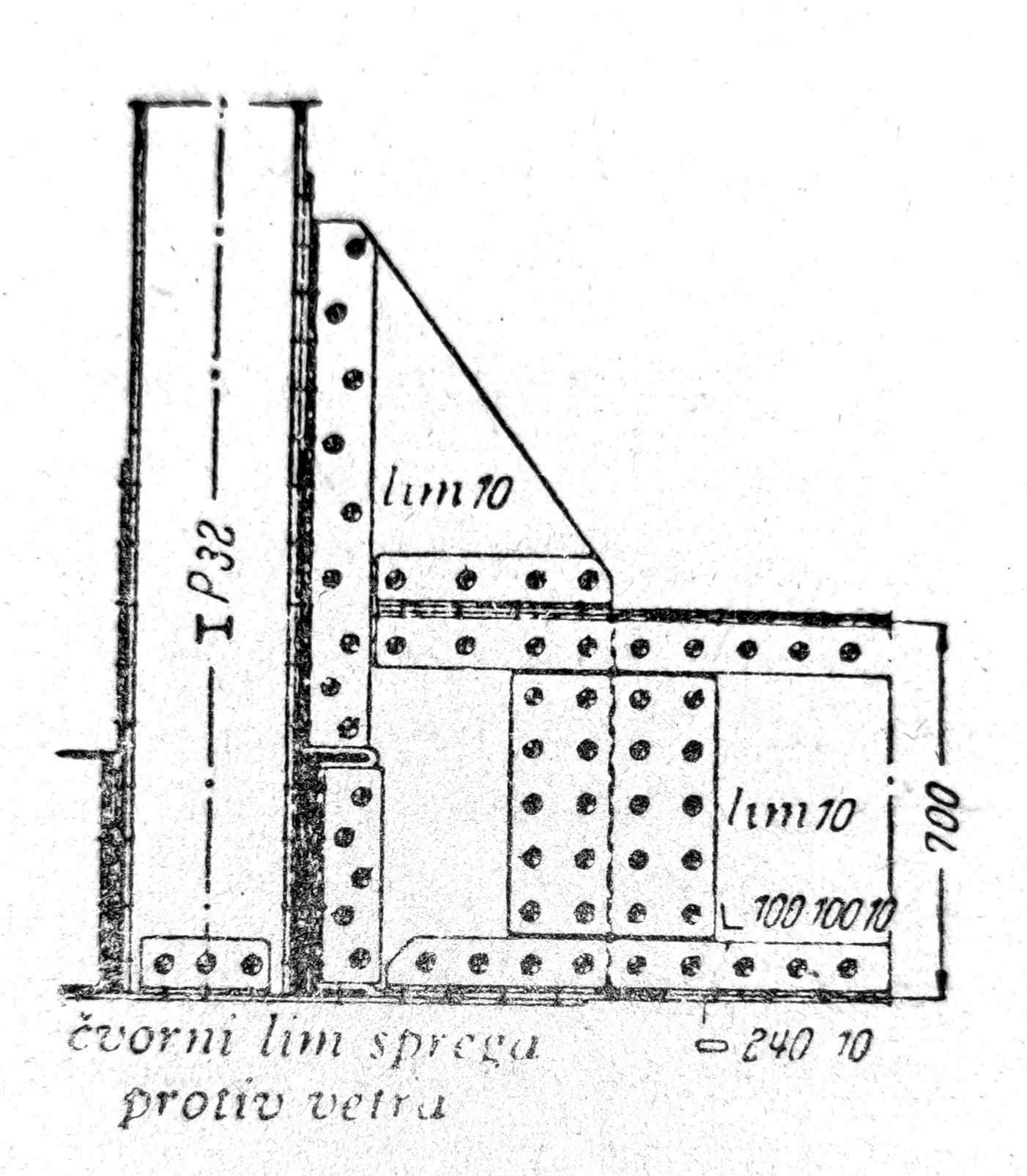
Fig. 12 — Crossbar connection
In the event that the pavement is down, the connection is made with simple connection angles, or road plates, which are inserted into the cross member (fig. 12), or in the verticals of the I-section, and in place of their ribs (fig. 13). The solution in fig. 14 is particularly rigid, since there the cantilever sheet is embedded both in the cross member and in the vertical, so that the moment at the corner is received by the shear bolts. With other solutions, it cannot be avoided that the screws partially tear and that the connection angles are bent. Connections according to fig. 12 and 13 are significantly more deformed under the influence of the moment than those according to fig. 14. Similar solutions arise for other pavement positions. Laying of transverse supports on the main supports is possible only with sufficient structural height. Then the sheet metal main supports should be stiffened in the places where the load is applied.

Fig. 13 and 14 — Transverse support connection variants
Longitudinal supports
Longitudinal supports can be under the roadway and under pedestrian crossings. The outer girder, which is often connected to the bridge railing, is called the edge longitudinal girder. Longitudinal supports are made of rolled and sheet metal supports. Their range is up to 12 m. Since the longitudinal beams are exposed to the most direct influence of the moving load, their rigidity against bending is particularly important. In the case of railway bridges, the height of the girder from 1/8 to 1/10 span is aimed for. Longitudinal supports made of high-quality steel are generally unsuitable due to high bending. In many old bridges, the connection of the longitudinal girders was carried out according to fig. 15. One connection angle lies between the legs of the rolled support, while the other rests on the entire height of the cross support. With these types of connections, significant secondary stresses occur, and in many cases, fatigue breaks have occurred with them, as well as cracks at the point where the leg is cut. For this reason, such connections are not allowed at railway bridges. If cutting the leg cannot be avoided, these cuts should be made with a large rounding, in order to avoid the risk of cracks.
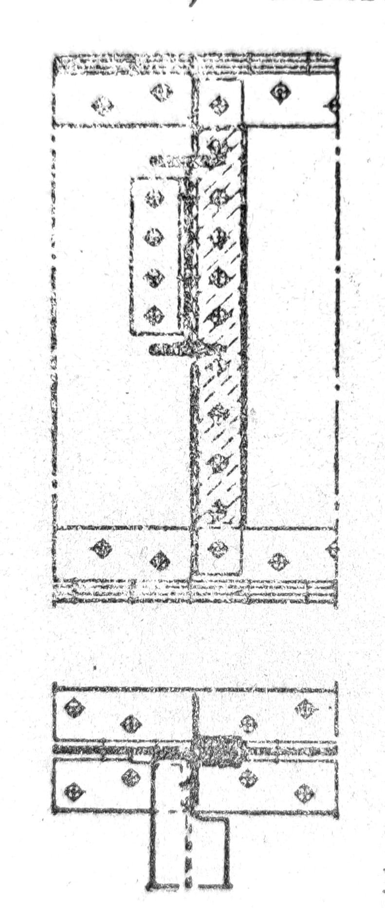
Fig. 15 — Longitudinal support connection
Drainage
Great attention should be paid to the drainage of bridges. Quick and complete drainage of water is the most important prerequisite for the long life of the road surface, as well as the bridge itself. In addition to increased rusting and increased maintenance costs, water retention areas are also dangerous due to frost damage. If the level of the bridge allows it, the road bridges should have a certain longitudinal drop (not less than 1%), which would ensure the flow of water to the drain. Water contaminated with oil and dust is drained away through gutters. These gutters must have sufficient longitudinal fall and must be accessible, so that they can be cleaned regularly.
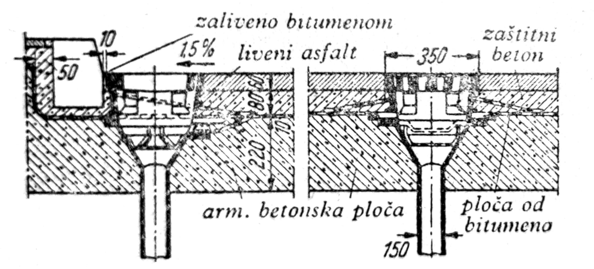
Fig. 16 — Drainage and protective layers of road surface
Asphalt pavements are not absolutely impermeable. Special insulation under the asphalt can be dispensed with if the asphalt lies on a concrete slab that has been vibrated, and that slab itself is largely impermeable. If the pavement is not sufficiently impermeable, so that a part of the storm water penetrates, insulation should be provided. For steel bridges, coatings of asphalt bitumen or terra etc., insulating layers of bituminous insulating masses with solid inserts of paper with wool felt or jute weaving, as well as insulating layers of metal foils of copper or aluminum are considered. Insulation layers must be protected from mechanical damage with protective layers.
Descriptions of falls, gutters, asphalt, concrete slabs, bituminous masses, felt, jute and metal foils are historical. Modern drainage, waterproofing, steel protection, penetration details and maintenance are designed as a coordinated system according to current regulations, climatic conditions, traffic and actual construction.
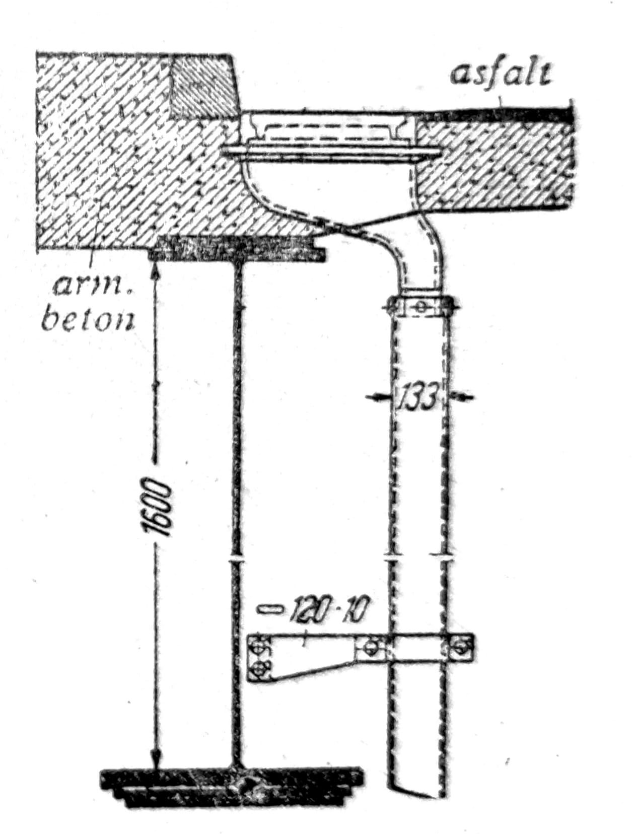
Fig. 17 — Detail of drainage along the edge of the bridge
Couplings
Sheet metal girders have little rigidity in the direction perpendicular to the plane of the girders, grids with assumed joints in the nodes are even multiple movable in the transverse direction. Therefore, wind braces and cross frames are needed to create spatially stable structures first. Furthermore, they should receive loads that act transversely to the plane of the main supports, and finally ensure the construction against buckling and overturning.
Couplings against the wind
These couplings are dimensioned to receive forces from wind and other horizontal loads. They consist of grids or frame supports, straight or curved according to the belts. Belts of couplings against the wind are mostly also belts of the main supports. Often the transverse supports are also the verticals of the coupling against the wind.
A less wind load is assumed for a loaded bridge than for an unloaded bridge. If the cross-section allows it, truss bridges preferably have two wind braces between the girders of the main girders. See system sketches in fig. 18 in which upwind couplings and transverse couplings are marked with dashed lines.
The number and type of transverse couplings must be sufficient to create a spatially rigid system. It is common for grids to ensure stability in the case of ball joints as well. Ports and Gerber beams, with the exception of small bridges, are stiffened with special couplings against wind and against buckling. At the joints of the main supports, the couplings must be made in such a way that they do not affect the action of the joints, fig. 18th century
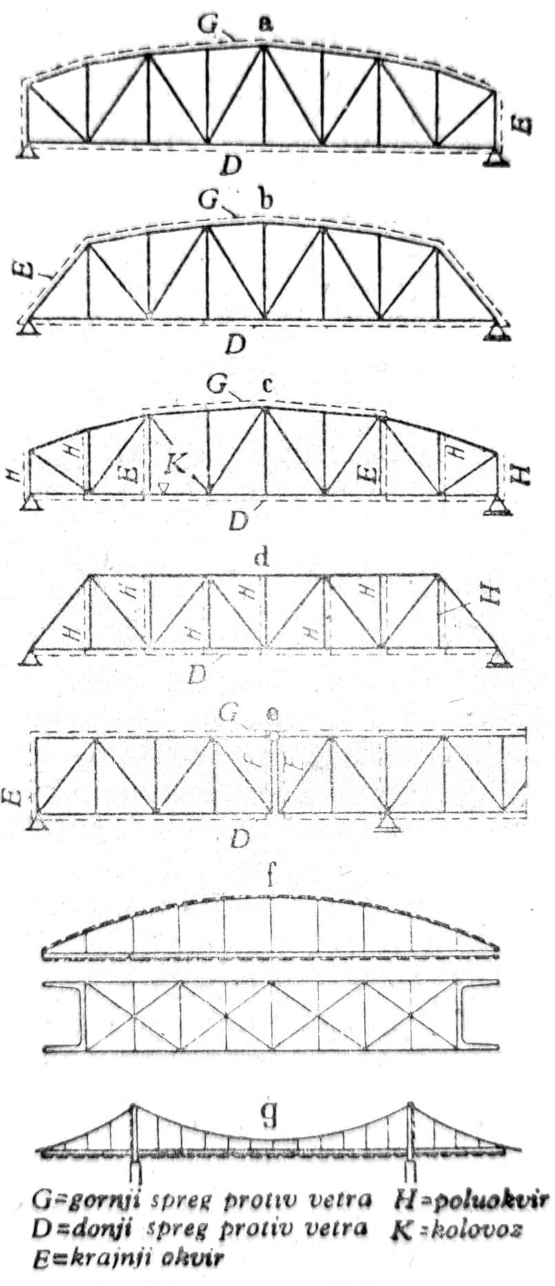
Fig. 18 — Arrangement of couplings against the wind
Wide pavement boards made of sheet metal or reinforced concrete are very rigid in their planes. If the spans are not too large, special couplings against the wind can be omitted, since the appropriate role can be taken by the pavement board. Only during assembly must measures be taken to absorb transverse forces.
When choosing the infill, it should be borne in mind that the forces in the members are generally small while their buckling lengths are large. Therefore lattices with short member lengths, such as a K-system or rhombic system, are preferred. Sometimes, the wind bracing is suspended from the roadway supports in order to reduce the buckling length. For bracing above the roadway, the rhombic system without verticals is often used.
The height position of the coupling against the wind is determined mainly by structural conditions (fig. 19). If possible, an eccentric connection is avoided here as well. especially with high forces, and the coupling against the wind is set in such a way that the shafts of the rods intersect in the planes of the main supports (fig. 20).

Fig. 19 — Altitude position of the antiwind coupling

Fig. 20 — Antiwind Coupling Node
Cross frames
Bridges with the roadway up can be stiffened with light lattice frames according to fig. 22. Transverse couplings in the form of a frame can be connected to the main stiffeners of sheet metal beams. In fig. 21 many lines are placed over the tension frame on two joints, i.e. over the grill under the cross member, so that they are accessible from the middle revision track.
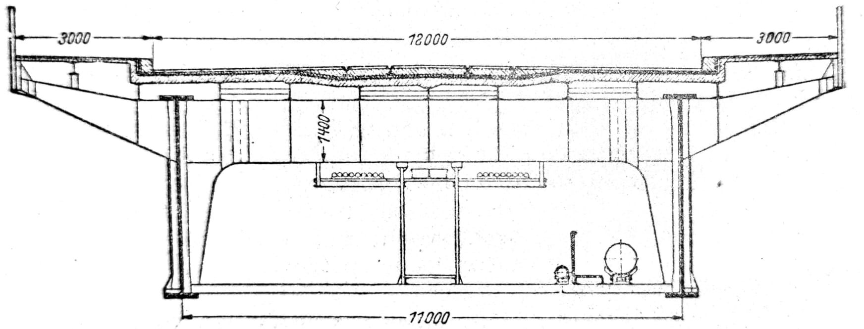
Fig. 21 — Transverse frame and installation guidance

Fig. 22 — Lattice Cross Frame
In the case of bridges with the carriageway below, the shape of the transverse frames is determined by the free profile for the passage of vehicles. Bridges with lattice transverse frames are shown in fig. 23d. Transverse frames that distribute the load (fig. 24) are needed for grills in order to engage the cooperation of all the main supports even for a partial load. If it is a railway bridge with a curved track or if the main girders are in a curve, this should be taken into account during the static calculation of couplings.
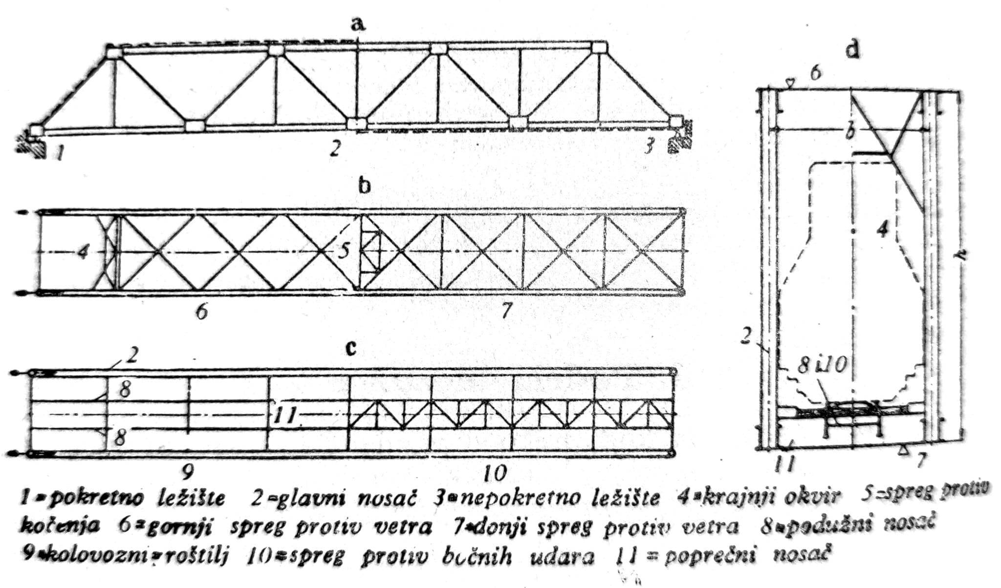
Fig. 23 — Examples of transverse couplings and main supports
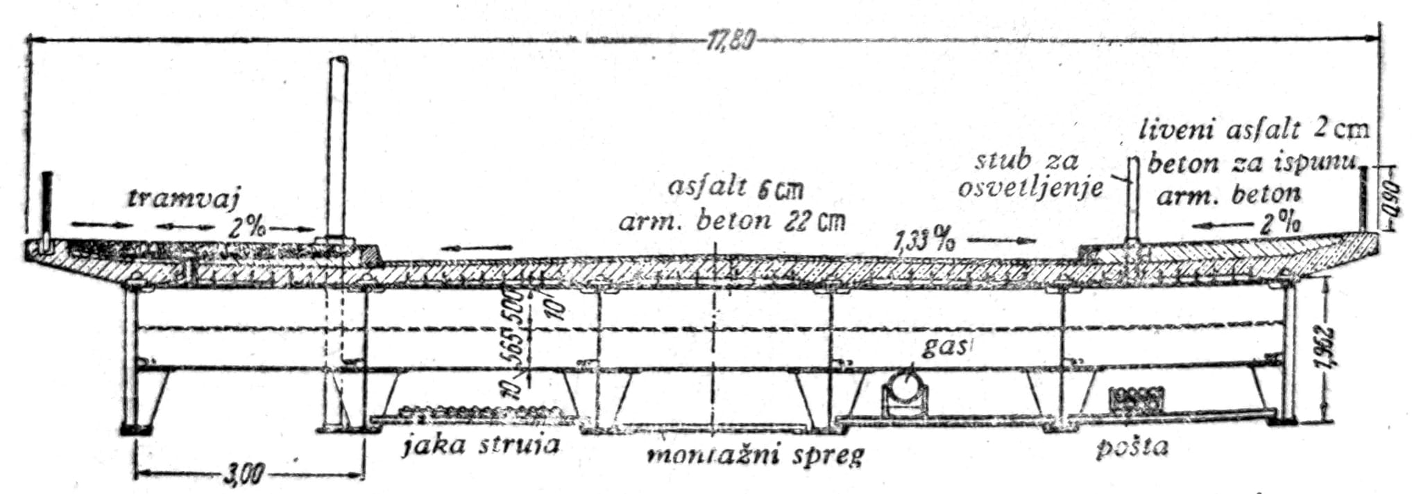
Fig. 24 — Cross-section and cross-beam for load distribution on the Ruhr bridge at Herdecke
Side impact clutch
Between the longitudinal supports of railway bridges (fig. 23c) it is necessary to provide a special coupling for the reception of side impacts of vehicles. I-longitudinal girders are proportionally very little rigid in the transverse direction, so it is desirable that the coupling against lateral impacts increases their safety against lateral buckling (fig. 25).
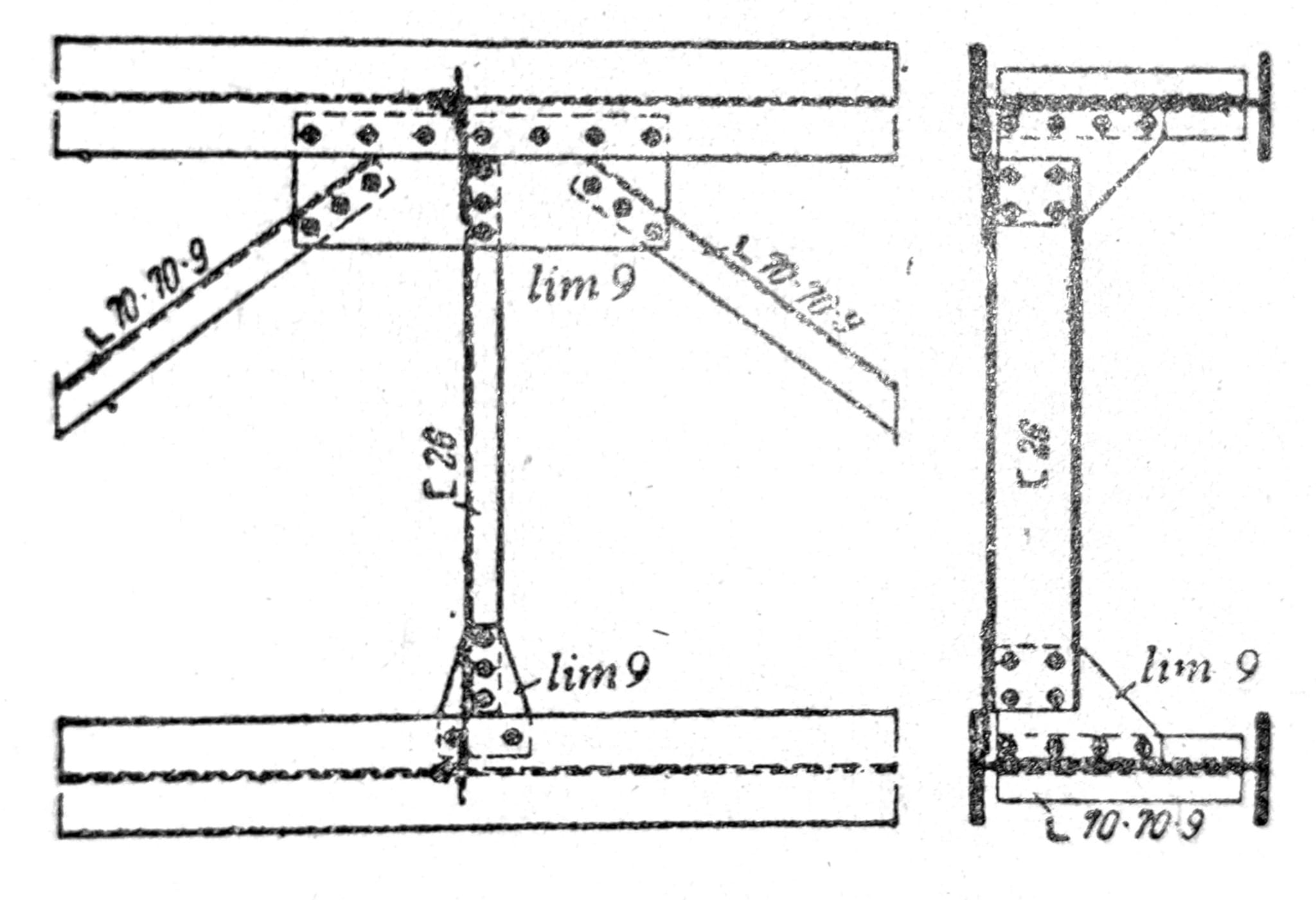
Fig. 25 — Side impact coupling
Anti-braking clutch
Transverse girders are not able to receive the forces acting in the longitudinal direction of the bridge, which occur when braking or starting to drive the vehicle, and they should be relieved by installing anti-braking couplings. They are grid flat girders (fig. 26) that connect the longitudinal girders with a coupling against the wind (fig. 27). There is often a height difference between the carrier and the coupling. And in cases where the length of the supports can be directly connected with the anti-wind coupling, a special anti-braking coupling is needed, since the rods filling the anti-wind coupling are not able to receive a significant bending load. In some cases, it can be combined into a single track anti-wind coupling, anti-side impact coupling and anti-braking coupling.
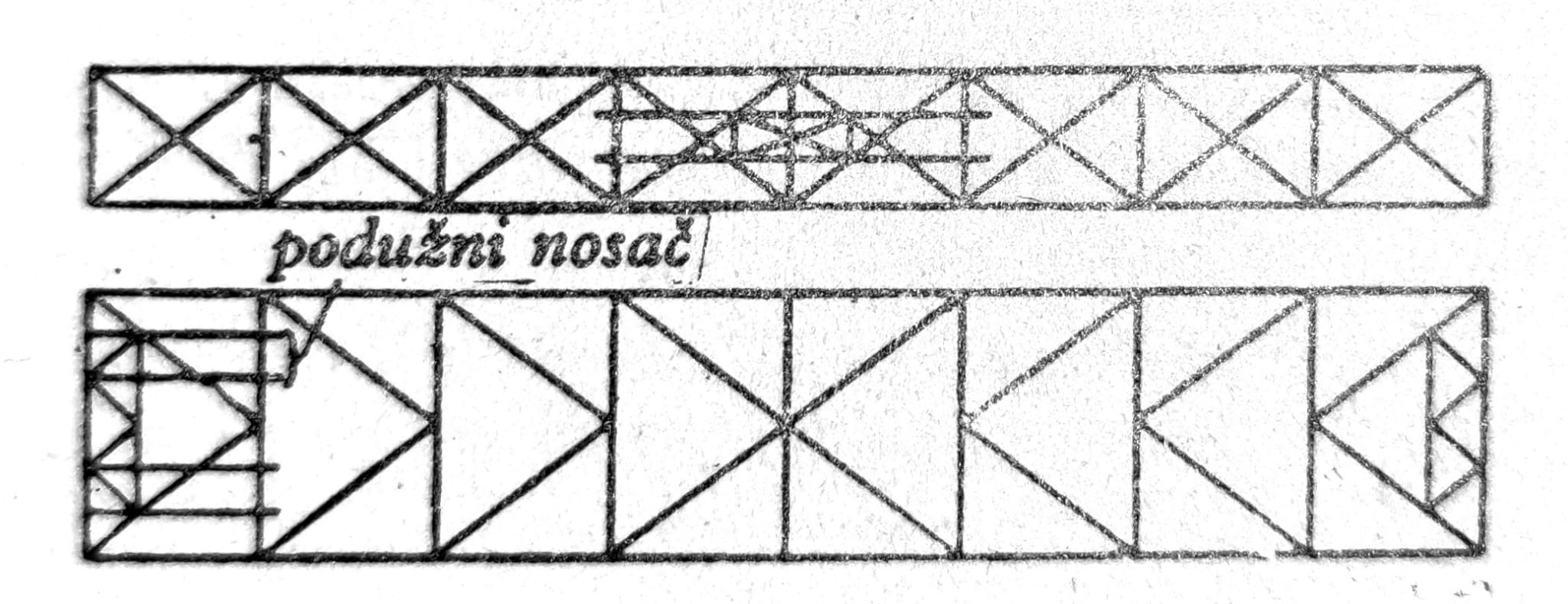
Fig. 26 — Anti-braking clutch system

Fig. 27 — Anti-braking clutch