Archival expert content: text and scanned formulas preserve a historical theoretical account, but are not a geotechnical study, retaining wall project, stability calculation, assessment of an existing wall, excavation plan or execution instructions. Earth and water pressures depend on the specific soil, layering, compaction, drainage, groundwater, geometry, wall movement, additional loads, frost and seismic action. For each actual case, investigative work, laboratory data, valid standards and joint verification by a licensed geotechnical and structural engineer are required.
Today, Savo Kusić is focused on wooden windows, wooden-aluminum windows, custom windows, doors and requests for quotation. This article remains a historical archive and does not represent an offer of geotechnical design, calculation or construction of retaining walls.
Earth pressure on retaining walls
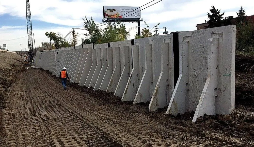
The earth mass supported by the retaining wall exerts pressure on it, tending to push it translationally forward (fig. 1a) or to crush it (fig. 1b). The magnitude of the earth pressure E depends on several factors, among which the most important physical properties of the soil, deformation of the wall, soil moisture and groundwater condition, height of the wall, external load and roughness of the inner surface of the wall.

Figure 1 — translational movement and rotation of a retaining wall.
Earth pressure at rest
If the retaining wall is rigid and immovable, the pressure acting on it is called the earth pressure at rest and is denoted by E0. This is exactly the pressure that prevails in undisturbed soil at the observed depth, under the influence of the soil’s own weight and possibly the preloading of previously eroded layers. Earth pressure at rest is rare and occurs only in certain cases, such as with retaining walls founded in solid rock, then with closed profiles of tunnels and pipes, and with massive docks, which are completely immobile (Fig. 2).

Figure 2 — earth pressure at rest on a massive dock.
Active earth pressure
If the retaining wall under the influence of pressure E moves forward or reverses around the foot point A, or some lower point, which are regular cases in compressible soil, with the exception of the aforementioned closed and massive structures, then the soil mass behind the wall expands. If the movement of the wall is large enough, one part of the soil behind the wall, the prism ABCA, breaks off and slides down the sliding surface AC (fig. 2). The pressure exerted by the sliding prism on the supporting wall is called active earth pressure and is denoted by Ea. This pressure is significantly lower than the resting pressure, about 0,5 to 0,7 E0. Due to the sliding of the earth prism ABCA, shear stresses τ are activated along the formed sliding surface AC, which oppose the sliding and reduce the earth pressure. At the moment when prism ABCA begins to slide, shear stresses τ reach their highest value, which means that at that moment the value of active earth pressure E is the lowest. Therefore, Ea is the lower limit value of earth pressure.
Terzaghi’s tests of earth pressure with sandy material on a wall with a height of h=1,50 m showed that to reach the lower limit value of active earth pressure Ea, medium horizontal displacement of the wall Δl of 5/10.000 wall height or rotation of the top of the wall Δl of 1/5.000 h around the leg A.
Passive earth pressure
If we apply pressure on the wall from the outside towards the inside of the soil (fig. 3), the wall will move backwards and the soil will compact. When the movement of the wall reaches a certain value Δl, the earth prism ABCA will be separated from the ground, which will be pushed upwards by the sliding surface AC under the further action of the external force. The resistance that the soil provides against the action of the external force at the moment of separation of the prism ABCA is passive earth pressure Ep. It is the highest upper limit value that the earth pressure can reach.
Earth pressure at rest is determined experimentally, while active and passive earth pressure can be determined computationally, using analytical or graphical methods, based on knowledge of the physical characteristics of the soil, usually determined by laboratory means.

Figure 3 — passive earth pressure and the sliding wedge.
Important for implementation: active, passive, and idle states are not selected by construct name alone. Permissible wall displacement, effective stresses, drained or undrained conditions, groundwater level and change, additional loads, and potential for soil loss in front of the wall must be demonstrated. The wrong choice of pressure conditions can compromise the sliding stability, overturning, bearing capacity of the soil and the strength of the wall.
Determination of the coefficient of rest pressure K0
In the case when the retaining wall is exposed to the effect of static pressure, for the dimensioning of the retaining wall, the static pressure E0 should be adopted, which is greater than the active earth pressure. Its size is between active and passive earth pressure, depending on the type of soil and its compaction.
At the depth t below the ground surface, the vertical pressure from the soil’s own weight is σt = γ·t. If there is no possibility of lateral soil expansion, horizontal pressure σh = γ·t·K0, acts at the depth t where K0 = σh/σt.
K0 is the resting pressure. The coefficient of rest pressure can be determined by the triaxial test as follows.
A sample of undisturbed soil taken from the depth of the resting pressure is placed in the triaxial apparatus, where the lateral pressure σ3 when applying the vertical load σ1 is adjusted so that lateral deformations do not occur, i.e. that the lateral deformation of the sample is equal to zero. The values of the effective voltages σ’1 and σ’3 obtained in this way are applied to the diagram σ’1 – σ’3 (fig. 4), and a straight line tangent to the initial part of the diagram is obtained, the slope of which determines the value K0 = σ’3/σ’1.

Figure 4 — determination of the at-rest pressure coefficient K__0 by a triaxial test.
According to Petermann, the approximate values of the coefficient of rest pressure are
for compacted sand K0 = 0,40 – 0,45
for loose sand K0 = 0,45 – 0,50
for clay K0 = 0,60 – 0,75
Laboratory values: The approximate ranges below remain part of the original text, but are not a substitute for representative sample testing, geological model and design values. OCR notation of formulas, subscripts and apostrophes must be checked against an authoritative source before any calculation.
Methods of determining active earth pressure — Coulomb’s theory
Coulomb was the first to publish the theory of earth pressure (1770. year), based on field experience. He looked at the retaining wall supporting the loose soil. At one point, he removed the wall, whereby the earth mass slid along a sliding surface AC, inclined at an angle a with the horizontal (fig. 5). The weight W of the sliding earth prism ABC, limited by the terrain surface BC, the sliding surface AC and the supporting wall AB, acts simultaneously on the supporting wall and on the sliding surface. The amount of active earth pressure Ea was determined by Coulomb under the following two assumptions:
-
that the sliding surface is a real surface;
-
that the three acting forces: the weight of the sliding prism W, the resistance of the supporting wall Ea and the frictional resistance Q along the sliding surface AC intersect at one point, which means that the plane of forces is closed. According to this assumption, in the state of limit equilibrium the weight W is simultaneously canceled by the resistance of the supporting wall Ea and the frictional resistance Q along the sliding surface.

Figure 5 — determination of active earth pressure according to Coulomb theory.
The previous assumptions do not correspond to reality. The sliding surface is not a straight but a curved surface. The intersection of the three acting forces exists only in one case, when the surface of the terrain behind the wall is horizontal, the inner surface of the wall is vertical and the direction of the force Ea is horizontal, while it does not exist in the other cases. However, despite these deviations, the determination of active earth pressure is still based on the Coulomb theory, as it has proven to be practically usable in many cases.
To determine the active earth pressure Ea Coulomb assumed that due to the effect of the weight of the earth mass W there was a movement of the supporting wall and the formation of a prism ABC of active earth pressure. Assuming that the internal resistance of the soil consists only of friction. Coulomb decomposes the weight W into two components, one in the direction of the active earth pressure force Ea, the other in the direction of the resultant of the frictional resistance Q along the sliding surface (fig. 5b). In doing so, Coulomb further assumes that the component acts at the angle of internal friction with the normal to the sliding surface AC, and that the component Ea acts at the angle of deviation δ with the normal to the inner surface of the wall AB. The force W is determined by direction, magnitude and direction.
For a given sliding surface at an angle α with the horizontal, the force W is obtained from the surface of the ground prism ABC for the length 1,0 m perpendicular to the plan and the volumetric weight of the soil γ, W=AΔABC x 1,00 x γ. The forces Ea and Q are known by their directions. Based on the plan of forces (fig. 5b) and the sine theorem, we have:


Figure 6 — case in which the acting forces intersect at one point.
This form is correct only in the case when the terrain is horizontal (v=0), the inner surface of the wall is vertical (θ=0) and the force direction Ea is horizontal (δ=0) i.e. when the wall is completely smooth (fig. 6).
For this special so-called Rankine’s case we have:

The weight W is in this case W = 0.5·γ·h_2/tg_α, where γ is the volume weight of the soil.
If we introduce the previous value into the equation for Ea, we get:

The previous equation refers to an arbitrary sliding surface AC. However, the force Ea for the critical sliding surface should be determined, i.e. the one on which sliding is most likely to occur. It will be the surface that gives the highest value of active earth pressure max Ea.
For a given wall height H and adopted constant angle of internal friction ϕ, the value of active earth pressure varies with the angle of inclination α of the sliding surface to the horizontal. We will get the max Ea value if we differentiate Ea by α and set the differential equal to zero:

The formula is not a calculator: scanned equations may have illegible exponents, subscripts, angles and signs. They are not copied into the project without comparison with a reliable expert source, checking of units, model assumptions and independent control of the results. The calculation must include water, drainage, loads along the crown of the wall, seismic action and all relevant limit cases.
Determination of angles ϕ and δ
The angle of internal friction ϕ is determined in the laboratory. Its size depends on the type of soil, humidity and compaction. For certain types of soil, the value of the angle ϕ is mostly within the limits given in the table 1.

Table 1 — approximate values of the angle of internal friction ϕ for individual soil types.
The angle of deviation δ of the force Ea from the normal to the inner surface of the wall depends on the deformation of the wall and the soil behind it and on the roughness of the inner surface of the wall. If the settlement of the ground is greater than the settlement of the wall, which is the most common case, then the angle δ is positive, the friction between the wall and the ground acts upwards. If the settlement of the wall is greater than the settlement of the soil, which is an exceptional case, then the angle δ is negative, the friction between the wall and the soil acts downwards. The limit values of the angle δ are for a completely smooth wall surface δ=0, for a completely rough δ=ϕ. Generally, δ=2/3_ϕ_ is adopted, with the fact that the soil of the wall is permanently protected from strong wetting. If the soil behind the wall is exposed to strong earthquakes, δ=ϕ/2 is adopted, and if it is highly waterlogged δ=0.
Project values of angles: tabular and descriptive values _ϕ_ and δ are not directly applied to a specific location. The choice of parameters must correspond to the type and condition of the soil, the method of installation and compaction, drainage, the expected movement of the wall, the roughness of the contact and the relevant project approach.
Distribution of earth pressure behind the wall and point of attack of force Ea

Figure 7 — earth-pressure distribution when the retaining wall rotates about toe point A.
The distribution of earth pressure along the inner surface of the wall depends on the deformation of the supporting wall, on the shape of the soil surface behind the wall and on the shape of the inner surface of the wall.
The attack point of the active earth pressure Ea depends on the pressure distribution along the inner surface of the wall and on its shape. It is always at the height of the center of gravity of the surface of the pressure diagram.
Coulomb adopted that the earth pressure behind the wall increases linearly with depth, as with water, the so-called. hydrostatic distribution of earth pressure (fig. 7). However, the hydrostatic pressure distribution exists only in the case when the wall rotates around the leg A or some lower point, while in all other cases it deviates from it.
If the retaining wall rotates around the foot point A, or some lower point, the soil moves downwards (fig. 7a), while there is no pushing towards the interior of the soil. In this case, soil sliding occurs along the surfaces of least resistance M1C1, M2C2… parallel to the sliding surface AC, which occurs when the rotation of the wall is large enough to form a sliding prism ABCA.
Therefore, in this case, the pressure increases proportionally with the depth, i.e. the earth pressure distribution is according to Coulomb hydrostatic. The active earth pressure diagram will be obtained based on the knowledge of the force Ea and the height of the wall h, since the force Ea is equal to the area of the pressure diagram abc (fig. 7b):
Ea=x·h/2, whence x=2Ea/h,
that is, since Ea = ½ γh2Ka, x = γhKa.

Figure 8 — earth-pressure distribution when the wall rotates about top point B or a higher point L.
If the supporting wall turns around the top of the wall B or some higher point L (fig. 8a), there is a push in the upper part towards the interior of the soil, which is consequently pushed upwards along the surfaces of least resistance M1C1, M2C2…
With a sufficiently large rotation of the wall, a sliding surface AC is formed, along which the sliding prism slides downwards during extrusion. Due to the pushing of the soil in the upper part, a passive earth pressure appears, which is significantly higher than the active one, and in that part the pressure diagram bd corresponds to the passive pressure Ep (fig. 8b). As the total earth pressure Ea depends on the size of the earth prism ABCA and is equal to the triangular surface of the pressure diagram abe, this diagram will decrease in its further course, until its surface becomes equal to the triangular surface abe. The actual pressure diagram in this case is curvilinear bc, which cannot be determined mathematically. However, the center of gravity S of the surface of the diagram ac is above the center of gravity of the surface of the triangular diagram, which is less favorable for the stability of the retaining wall, because the attack point of the force Ea is higher. According to Terzaghi, it is located at half the height of the retaining wall.
If the supporting wall is moved forward translationally (fig. 9a), the pressure that before the movement corresponded to the earth pressure in the resting state E0 decreases, whereby surfaces of lower resistance do not appear, but when the wall moves sufficiently large, a sliding surface AC is created, along which the earth prism ABC slides downwards. Since the total pressure is equal to the triangular area of the pressure diagram abe (fig. 9b), the pressure diagram will decrease in its further course. The actual pressure diagram is a curved line ac, which cannot be determined mathematically. According to Terzaghi, the center of gravity of S is at the height of 0,40 – 0,45_h_.

Figure 9 — earth-pressure distribution during forward translational movement of the retaining wall.
Considering the method of determining earth pressure as an extreme value, the largest for active and the least for passive, Coulomb’s theory is considered as an extreme method of determining earth pressure.
Final engineering note: the distribution and attack point of pressure depends on the actual way the structure is deformed. In addition to earth pressure, drainage and hydrostatic pressure, global and internal stability, sliding, displacement, soil bearing and settlement, wall and foundation strength, erosion, leaching, excavation phases and temporary stability must be checked. The condition of an existing wall showing movement, cracks, bulging or uncontrolled water leakage requires immediate professional assessment.