Archival Expert Content: The article preserves historical examples and claims of welded steel girders, bridges and trusses, but is not a design, calculation, joint specification, welding plan, procedure qualification, fatigue assessment or repair manual. Material, weldability, toughness, thickness, joint preparation, filler material, preheating, sequence, residual stresses, tolerances, corrosion, fire, fatigue and control must be determined according to the specific project and applicable standards. Bearing joints are designed, executed and controlled by suitably qualified persons.
Today, Savo Kusić is focused on wooden windows, wooden-aluminum windows, custom windows, doors and requests for quotation. This article remains a historical archive and does not constitute an offer to design, weld, test or strengthen steel structures.
Full welded brackets
Sections of supports
An overview is given by fig. 1 and 2. Sl. 1a shows a support reinforced with welded belt slats. Sections of arbitrary load capacity can be assembled from wide steel and sheets (fig. 1b to e). An open joint between corner seams should be avoided by sharpening the vertical sheet (fig. 1c). The cross-section of the support can be adapted to the required resistance moment with additional belt slats. Sections in fig. 2d to f have the advantage that the facing seam comes in an area of less rib thickness. Here, the seams can be examined particularly easily with X-rays.
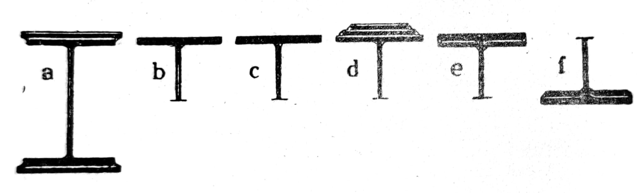
Figure 1 — sections of welded girders.

Figure 2 — girder sections made from special profiles.
Weld control: radiographic examination uses ionizing radiation and is performed only under controlled conditions by authorized experts. The choice of control method, scope of acceptance and quality criteria are determined by the project and standard; inspection of a photograph or external surface is not proof of the internal quality of the weld.
Continuation of the vertical sheet
The development took place in a completely appropriate manner. Extensions with garters were performed. The cruciform extension did not gain much importance in bridge construction, but it still proved to be good in building construction. Since the vertical extensions to the interface were uneconomic due to the small allowable stresses, extensions with an increased length of the seam were found.
Universal extensions
Sl. 3 shows the continuation of the main girder of a highway bridge with a reinforced rib. Sl. 4 gives a continuation of one highway bridge. At its best, this extension does not differ in appearance and mode of action from the non-extended support, only the fatigue strength is slightly lower. The extension solution depends on whether it is a workshop extension or an assembly extension. Since better tools are available in the workshop, welding on site is limited if possible. Sl. 5 shows the division of one 63m long beam. The supports were delivered to the construction site in sections of 38m and 25m in length, where only the extensions marked with “B” were welded. The mounting extensions are made as U-extensions, in order to avoid overhead welding.
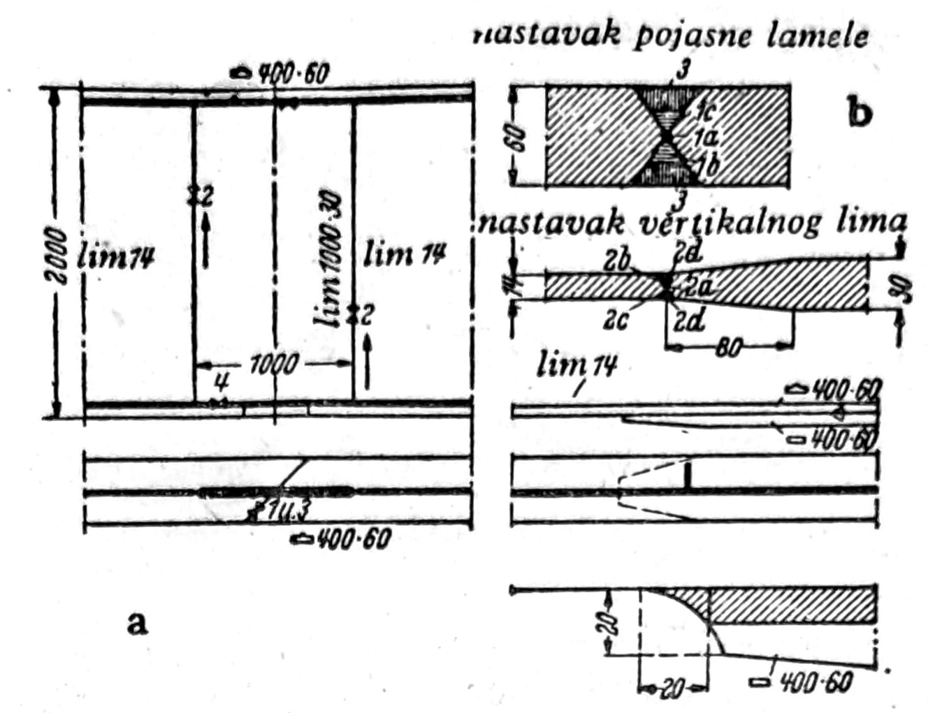
Figure 3 — bridge-girder splice on the motorway near Hattenheim.

Figure 4 — historical detail of a bridge-girder splice.
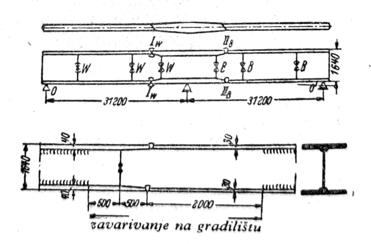
Figure 5 — arrangement of shop and erection splices.
Continuous full supports were welded during the progress of assembly along the openings without scaffolding, for example. near a road bridge with openings of 42 m. The parts of the support were installed with a floating crane and after the installation of all the elements, they were welded. At the same time, the main supports were fastened with screws using garters with openings (fig. 6). Through the holes in the garters, most of the seam of the vertical sheet could be welded, before the garters had to be removed. Sl. 6 contains further information on the preparation of U-seams for special profiles in the upper and lower belt.
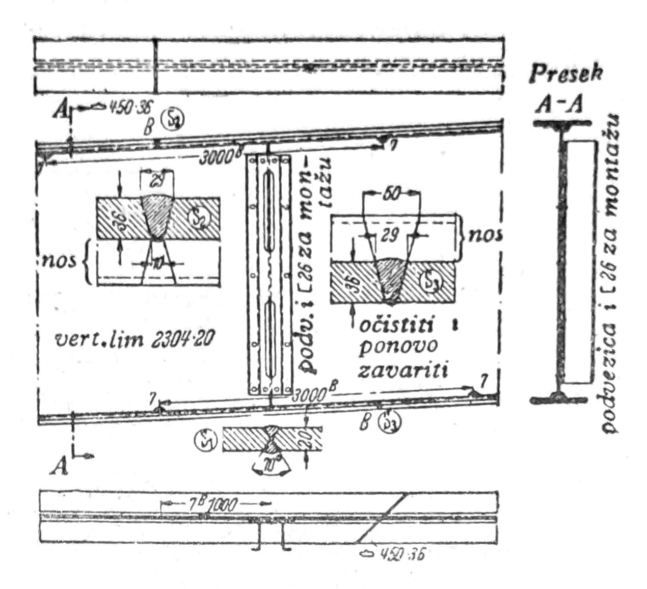
Figure 6 — temporary splice plates with openings for access to the weld.
Installation and site work: historical examples with floating crane, temporary ligatures, hatch work and site welding are not assembly plan. Calculation of temporary conditions, lifting and securing plan, geometry control, fall, fire and smoke protection and traceable control of each joint before removal of temporary supports are required.
Stiffeners
It is necessary to stiffen the solid welded supports well against the protrusion of the vertical sheet and lateral buckling of the belts, in addition, bending during welding should be kept at a low level. Shrinkage stresses on vertical stiffeners were investigated by O. Graph-a. During the examined sequence of works (stiffeners were welded first, then the main seams), significant shrinkage stresses occurred in the stiffeners and nearby strips of vertical sheet metal. If the stiffeners are already on the belts before the main seams are pulled out, then the shrinkage of the belt slats is prevented. In the belt lamellas, wavy bends up to 2mm appeared in the longitudinal direction, and about 0,25mm in the transverse direction (fig. 7). Therefore, there must have been significant bending stresses in both directions in the belt slats. The bearing capacity was limited by the occurrence of large deformations, not by the breaking strength of the lower belt. According to the results of the fatigue test, it is required for bridges to install well-fitting plates between the stiffeners and the belt, which are secured to the stiffeners with a butt weld. Stiffeners and connections are cut in such a way that the main seam remains free (fig. 8). In the building industry, in most cases, there is no doubt that the stiffeners are welded directly to the girders. It is better to avoid cutting the seams and piling them too much.

Figure 7 — deformation of flanges during welding.
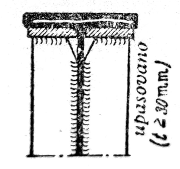
Figure 8 — stiffener with accurately fitted plates.
Shrinkage, deformation and fatigue: historical test results cannot be transferred to another detail without calculations. Stiffeners, weld terminations, seam crossings, tolerances, and work sequence affect residual stresses, buckling, and fatigue strength; unacceptable cracks and deformations are not solved by additional welding without an approved repair procedure.
Full mounts and frames
Arch supports and slender arches
Arch braces offer a little something special compared to true full braces. However, the connections of double-walled cantilever arches to single-wall stiffening beams, as performed on the two largest welded highway bridges, are among the most interesting constructions that have been welded. On the highway bridge over the Lech near Duisburg, a massive machined piece of forged steel was used at the end node to facilitate the welding work. This one (fig. 9) takes the forces from the arch and transfers them to the stiffening beam. It is supplied with a 50 mm strong outlet, which passes through a slot to the upper belt of the stiffening beam and which is welded to the vertical sheet, reinforced to a thickness of 50 mm.

Figure 9 — end joint of an arch bridge.
Frame constructions
The advantages of the welding technique are best seen on the corners of the frame, which allows complicated shapes to be made without particular difficulties. One corner of the frame with a heavy load is shown in fig. 10. The construction has welded workshop extensions. The mounting extensions are attached with self-tapping screws. When welding stiffeners between the legs of the joined supports, high shrinkage stresses occur, which sometimes lead to cracks. Shrinkage stresses are significantly reduced when only wing sheets (fig. 11b) are welded instead of full ribs (fig. 11a).
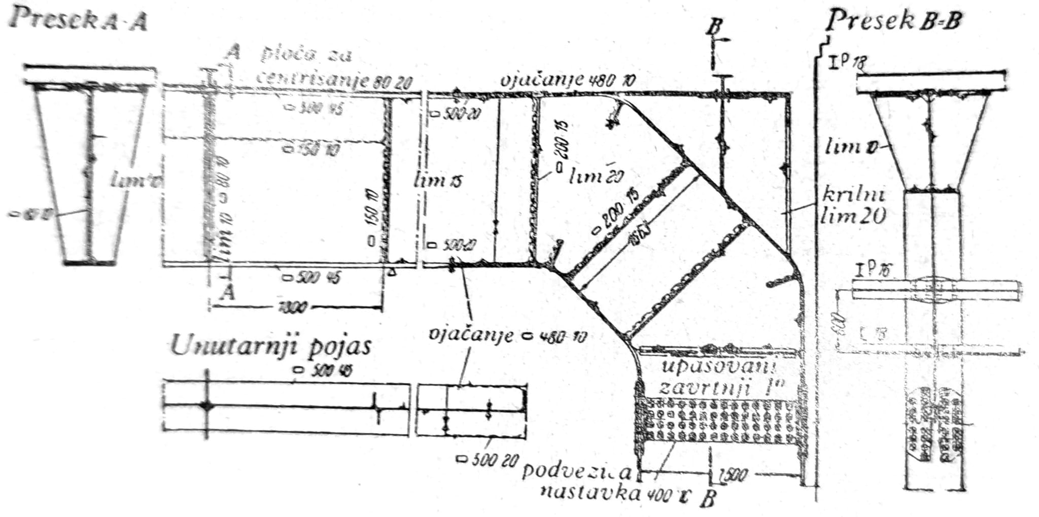
Figure 10 — corner of a frame girder.
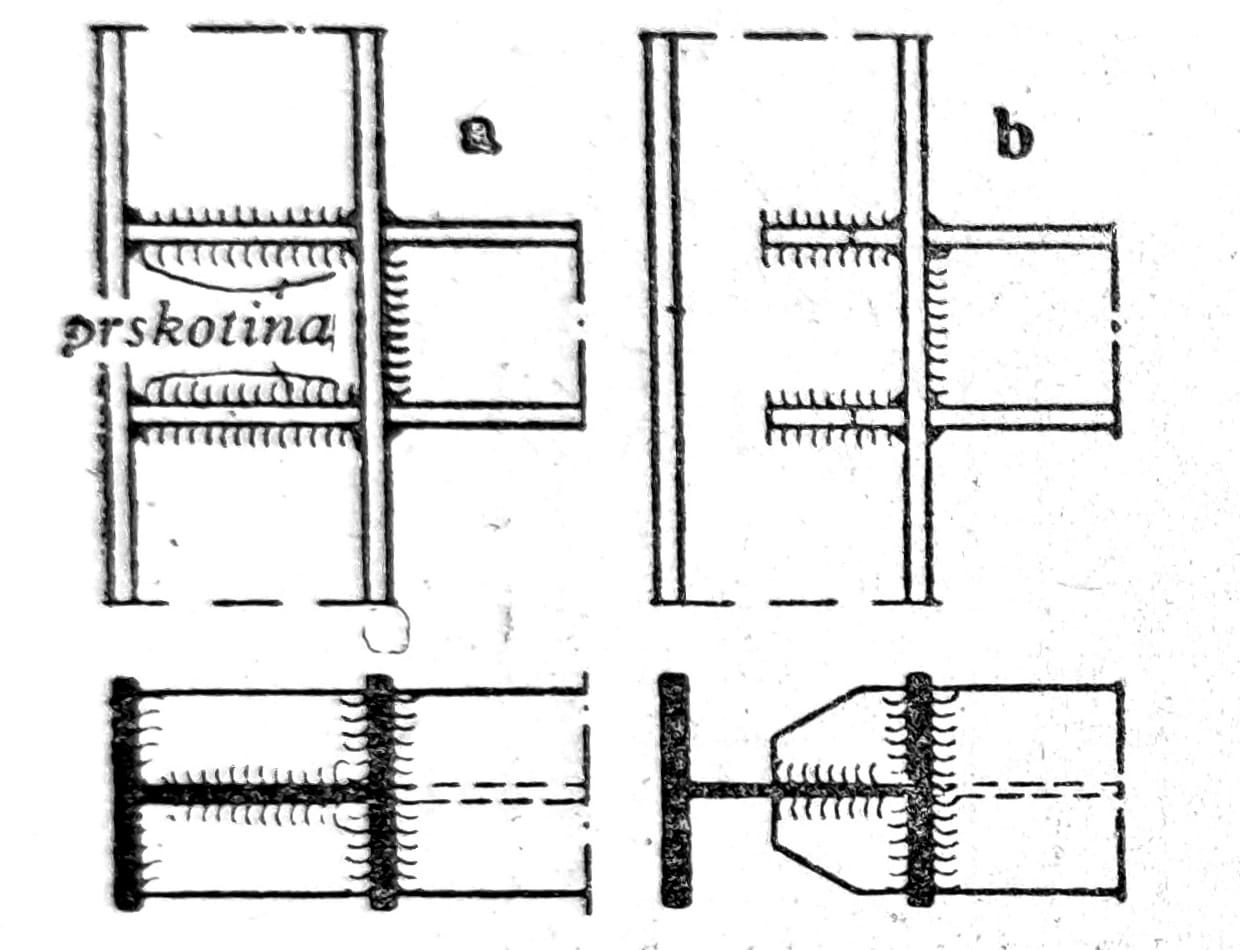
Figure 11 — comparison of stiffening details for a welded connection.

Figure 12 — joint of a Belgian bridge with frame girders.
The connections of the longitudinal supports are rigid in bending
A great simplification can be achieved in the pavement grid of bridges by using welded connections. Fatigue strength of connections of longitudinal supports, etc. under bending load, it is illuminated by tests O. Graph-a (fig. 13). Therefore, the connection with a seam to the interface on the tensioned side has a higher fatigue strength at the uniform bending stress σUb than the connection where the tensioned leg is connected by corner seams.
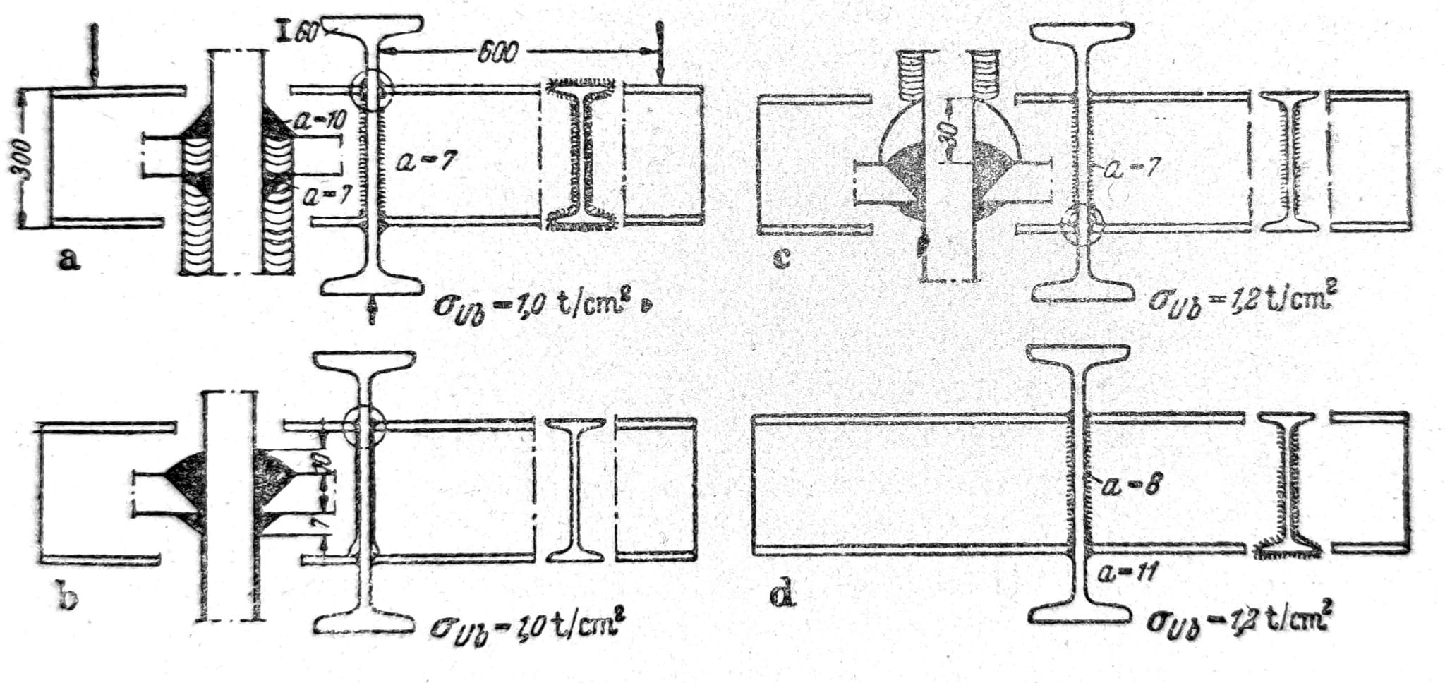
Figure 13 — historical variants of longitudinal-girder connections.
Lattice supports
Welded lattice structures
Older gratings were copies of riveted constructions in terms of shapes and connections (fig. 14). This is inexpedient, the special properties of welded connections must be taken into account when choosing the cross-sections. The greater stiffness of all connections compared to riveted nodes is also important. The connections of the diagonal rods in the nodes of the lattice are difficult to perform with higher forces, especially on the construction site. Since the connections with the corner seams come into question here in the first place, the fatigue strength is relatively low. Fully welded, ie. and in the nodes of the welded grid, therefore only in some special areas of steel structures. For example, with roof ties, with cranes not highly dynamically loaded, etc.
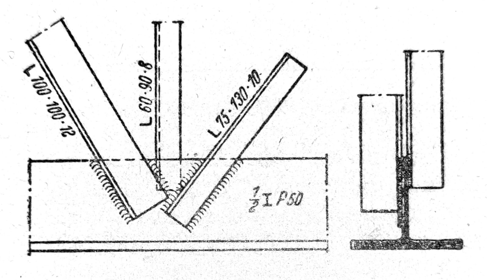
Figure 14 — welded joint of a truss girder.
For the formation of the cross-section, steel plates and sheet metal come into consideration in the first place. In the case of welded constructions, hollow sections are made without particular difficulty, which have the advantage of pressed rods due to their torsional stiffness. The special case of a round tube deserves special mention. Welded tubular constructions have found wide application, e.g. in the construction of cranes or light constructions in the building industry. In the case of continuation and connection of hollow sections, one must in fact take into account certain constructive difficulties and additional costs. Welded sections are often gathered at the ends so that the connection can be riveted more easily (fig. 15). The special measures required in the workshop and on the construction site for welded lattice structures make it difficult to apply, unless it is about supports with a slight or predominantly static load. For dynamically loaded grids and for those with high forces, the rule was that only individual elements were welded, but their mutual connection was done using screws. First of all, the installation difficulties were removed; and grids made of welded elements can be mounted according to the same procedures as those made of riveted rods.
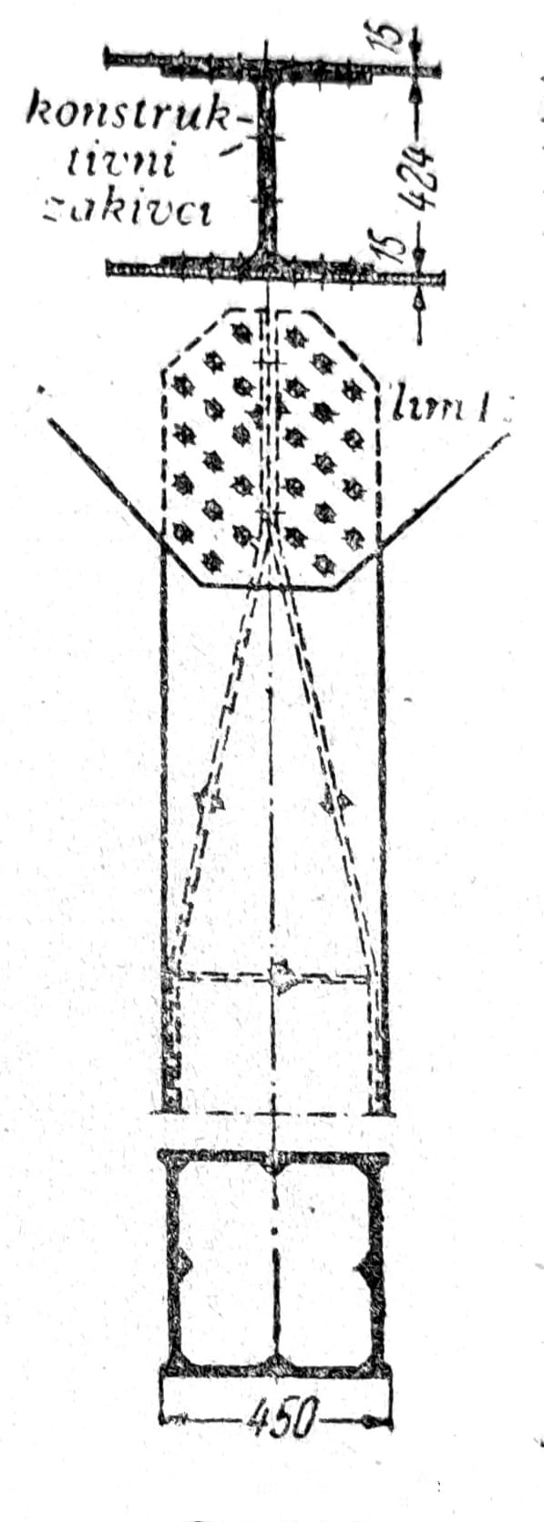
Figure 15 — shaping the end of a hollow section for a connection.
The knotted sheets, which receive the diagonals at the same time, are riveted in the usual way to the ribs of the belts or are butt-welded with them (fig. 16a). The latter has the disadvantage of “starting corner seams”, which are detrimental to the fatigue strength of the girder. A decisive step towards the correct shaping of truss bridges by welding was made at the railway bridge over the Rhine near Mainz (Kaiser Bridge). There, at 50 mm, reinforced nodal sheets are inserted into the vertical sheets of belts with a thickness of 30 mm by means of seams on the interface. The transitions are gradual, the shaping can be seen from fig. 16b. Belt rod extensions are located next to the nodes.
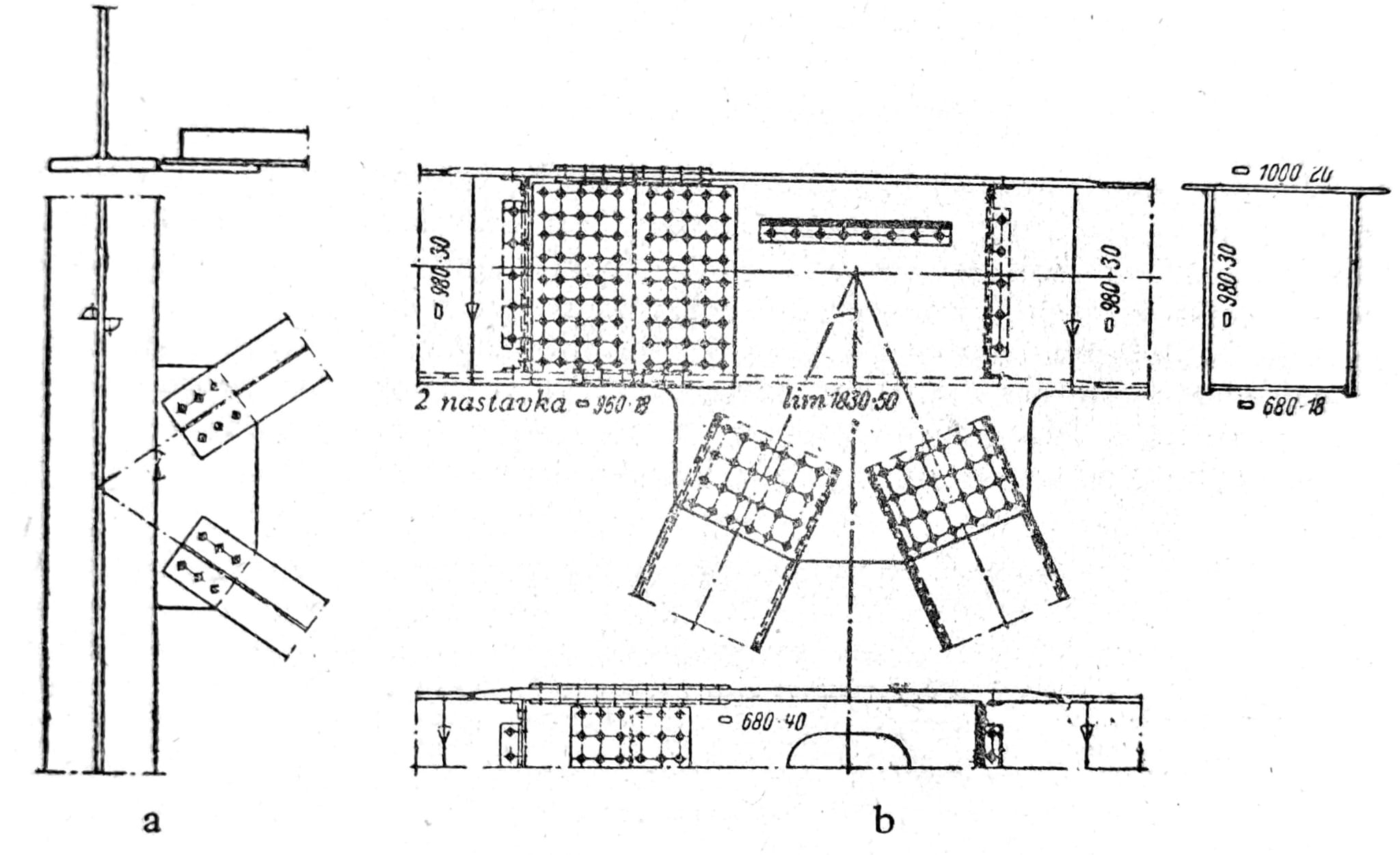
Figure 16 — gusset plates of a wind bracing system and the railway bridge over the Rhine near Mainz (Kaiser Bridge, 1954).
Reinforcement by welding
The subsequent strengthening of steel structures is considered one of the most difficult works, especially when it has to be performed on a loaded structure. With riveted connections, inserting reinforcements, drilling and connecting to existing parts is time-consuming and expensive. Since welding is possible without long-term preliminary preparations as well as without breaking the existing bonding means, it was close to try welding the reinforcement of the cross-sections and connections of the grids. The joint action of rivets and welds in receiving forces in rods has been examined in detail theoretically and in experiments. Nevertheless, in practical implementation, cracks and fatigue breaks appeared, partly only after prolonged use. The causes of these difficulties were the effects of welding notches and sudden changes in section, and some of the cracks that appeared were caused by high stresses from shrinkage.
Strengthening of existing structure: welding of stressed or aged steel can introduce cracks, brittle fracture, local loss of stability and new force path. Prior to work, the material, existing damage and fatigue, actual load, weldability, load relief sequence and temporary insurance must be determined. Reinforcement is performed only according to the approved project and procedure, with supervision and control.
Combining welding, riveting and screws
For some time it was forbidden to apply welding and riveting simultaneously. Special attention was paid to “fully welded structures” in which rivets and screws were completely avoided. Today, welding and riveting are again applied in parallel on the same object. In many cases, it is expedient to weld only the workshop extensions, and on the contrary, to rivet the prefabricated ones. The application of both types of connection in the same continuation should be avoided, because a clear distribution of forces cannot be achieved due to shrinkage related to welding and sliding of rivets/bolts.
Final note: the joint action of welds, rivets and screws must not be assumed without a calculation model, a defined sequence of execution, tolerances and slip control. For each load-bearing detail, the force path, fatigue category, accessibility to welding and inspection, acceptable defects and a maintenance plan throughout the life of the structure must be known.