Important Warning: This is a historical archive text, not a current machine specification, capacity calculation, risk assessment or operating manual. Tightening methods, models, dimensions, speeds, formulas, testers and procedures must be checked according to applicable regulations, manufacturer’s documentation and safe work rules.
This text is not an offer of machines, testers or service documentation of Savo Kusić. The current offer is focused on windows, doors and related solutions.
Tensioning the saw in the frame
With gutters, the saws must be well secured and tensioned in the frame. When working with weakly tensioned saws, a shard in the form of a wavy cut, etc. is obtained. The most common way of tightening the saw is by means of a wedge, eccentric, screw (picture 1), as well as the way of tightening using hydraulic devices. Tightening the saw with wedges is worse than other methods. A large number of industries produce a large number of types of powerful, fast-moving, highly productive saws. These highly productive sawmills work in large wood processing plants in the construction industry. The technical characteristics of these gaiters are given in table 1.
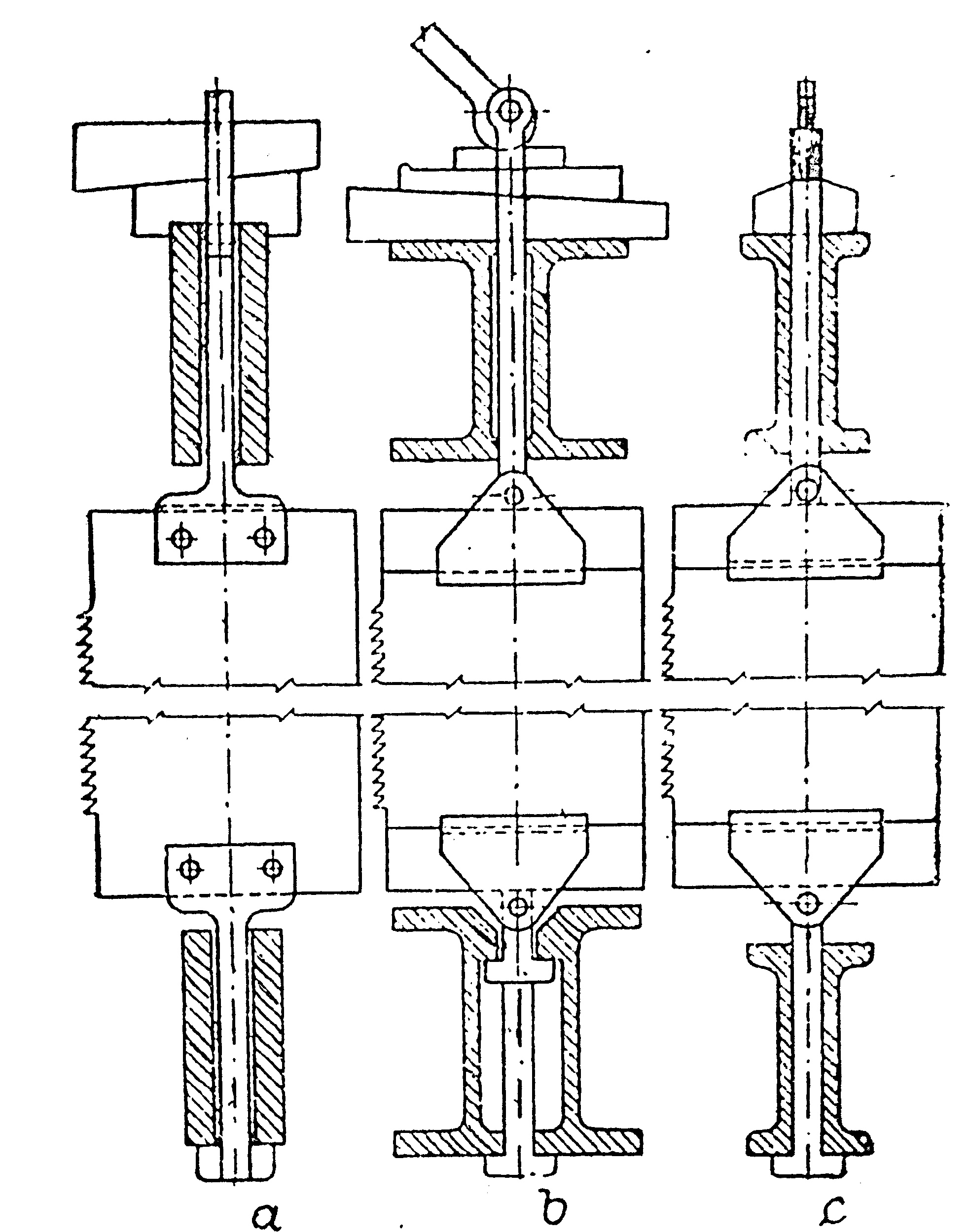
Image 1: Tensioning the saw in the gater frame
The main types of high productivity garters
| Technical indicators | Unit of measure | Types of Gaters | |||||||||
|---|---|---|---|---|---|---|---|---|---|---|---|
| With one crankshaft | With two workers | ||||||||||
| RD 75-2 |
RD 60-2 |
RD 50-2 |
RD 40-2 |
RLB 75 |
RD 110 |
R-65 | R-65-2 | Moving RP–65 | RK-65 | ||
| Opening width | mm | 750 | 600 | 500 | 400 | 750 | 1100 | 650 | 650 | 650 | 650 |
| Walk height | mm | 600 | 600 | 600 | 600 | 500 | 600 | 360 | 410 | 410 | 360 |
| Number of turnovers | rpm | 300 | 315 | 315 | 350 | 290 | 225 | 250 | 250 | 240 | 250 |
| Maximum displacement at 1 turn of gater shaft | mm | 45 | 45 | 60 | 60 | 22 | 20 | 20 | 20 | 20 | 20 |
| Moving system | Continuously | Intermittent | |||||||||
| Allowed number of testers in frame | com | 12 | 10 | 8 | 8 | 12 | 20 | 10 | 10 | 10 | 10 |
| Tier tilt mode | Combining constant pitch of the gater with variable pitch of the saw | Slope of the saw in clamps | |||||||||
| Number of rollers to start | com | 4 | 4 | 4 | 4 | 4 | 4 | 4 | 4 | 4 | 8 |
| Weight | t | 12 | 12 | 12 | 12 | 9 | 13 | 3,25 | 3,8 | 5 | 4,44 |
Light saws of low productivity are used for cutting logs in the conditions of rural construction and in smaller enterprises for the production of building elements from wood. The characteristics of these child gaiters are in the table 2.
Light gaiters
| Pointers | Unit of measure | Types of Gaters | |||
|---|---|---|---|---|---|
| RS – 50 | RS – 52 | GGS -2 | RP | ||
| Types | – | One-story with transmission from below | One-story with transmission from below | One-story with transmission from below | Movable single storey |
| Opening width Frame stroke |
mm mm |
500 300 |
520 400 |
534 300 |
550 400 |
| Number of revolutions Type of displacement |
rpm | 200 One-stop during the working stroke |
250 One-stop during the working stroke |
200 One-stop during the working stroke |
250 Bi-interrupted |
| Maximum Displacement Weight |
mm kg |
7,2 2000 |
10 3000 |
8 2500 |
15 6000 |
The productivity of the gater is calculated according to the formula: P = K - Δtnq/1000L m3. Where K is the gater utilization coefficient. For mechanized lathes K = 0.93, and for semi-mechanized ones K = 0.90; Δ - displacement for one turn of the gater shaft; n - number of revolutions of the gater shaft per minute; t - gater working time in minutes; q - log volume, m3; L - length of logs, m.
Historical calculation of productivity
When determining the average annual productivity of the gatekeeper for one shift, stoppages that occur due to various causes (repairs, lack of raw materials, etc.) must be taken into account. These losses are determined by the experimental coefficient Kgod = 0.9 - 0.92.
Therefore, the average annual productivity of a gater for one shift is determined by the formula P = Kgod x K x Δntq/1000L m3 for one shift.
Technical characteristics of gater testers are given in table 3.
Dimensions and profiles of gutter saws
| Length | Width | Thickness | The pitch of the teeth (the distance between the adjacent tips of the saw teeth) |
|---|---|---|---|
| 1100 | 150 and 180 | 1,2; 1,4; 1,6; 1,8; 2,0 | 15; 19 |
| 1250 | 1,6; 1,8; 2,0; 2,2; 2,4 | 18; 22 | |
| 1400 | 1,8; 2,0; 2,2; 2,4 | 18; 20; 22 | |
| 1500 | 2,0; 2,2; 2,4 | 22; 26 | |
| 1650 | 2,2; 2,4 | 22; 26 | |
| 1830 | 2,2; 2,4 | 22;26 |
Saws are made in two tooth profiles: with a broken back edge and with a straight back edge (fig. 2). When choosing the desired dimensions of the saw, you should be guided by the length of the frame of the gater, the size of its stroke and the diameter of the logs to be cut. The required length of the saw can be determined by the formula L = Dmax + H + (300 to 350) mm, where L is the length of the saw, mm; Dmax - maximum diameter of logs to be cut; 300 - 350 - supplement due to installation of inserts for boards and slats; H - stroke height, mm.
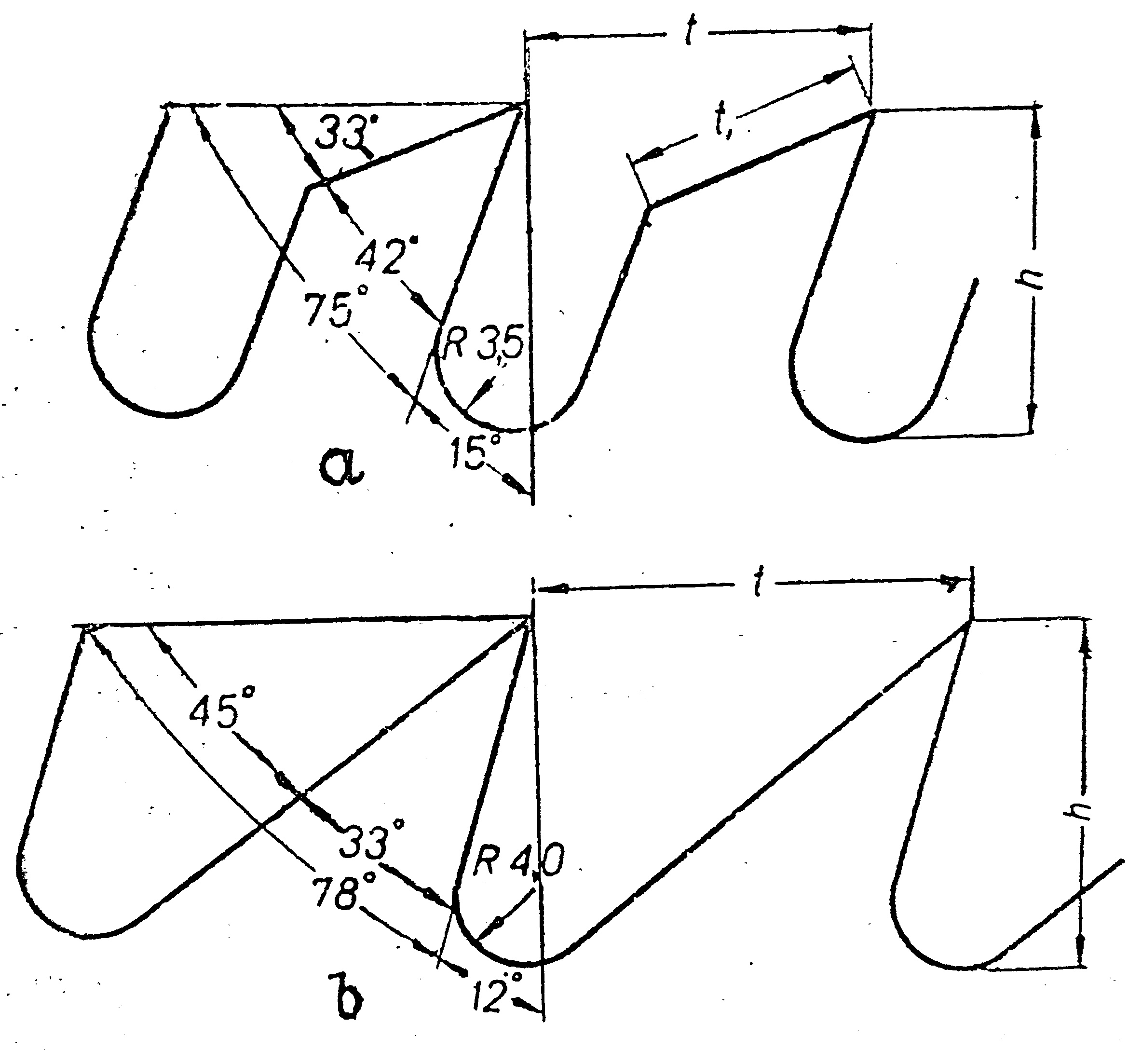
Picture 2: Profile of the teeth of the miter saws
The thickness of the saw and the pitch of the teeth should correspond to the height of the cut and the type of cut. This mutual relationship is given in table 4.
| Slicing type | Diameter at the thin end of the log or beam thickness, cm | Tooth pitch, mm | Saw thickness, mm |
|---|---|---|---|
| Cutting Logs Ditto “ “ |
Up to 20 21 – 26 27 – 34 35 and above |
15 and 18 18 22 26 |
1,6 – 1,8 – 2,0 1,8 – 2,0 2,2 – 2,4 2,2 – 2,4 |
| Cutting logs into beams Ditto “ “ |
Up to 22 23 – 24 35 – 44 45 and above |
15 and 18 18 22 26 |
1,8 – 2,0 1,8 – 2,0 2,2 – 2,4 2,2 – 2,4 |
| Beam cutting Ditto |
Up to 20 21 and above |
15 18 |
1,6 – 1,8 1,8 – 2,0 |
The saws are installed together with stirrups that attach to the lower end of the saw and with a set of two stirrups and seven bolts for the upper end. The stirrups are attached to the saw at right angles to its back edge. The beveled edges of the stirrup must be facing each other. Before riveting the stirrup, the edges of the saw should be checked to see if they are straight and parallel, and if they are not, they should be trimmed on a saw sharpening machine.