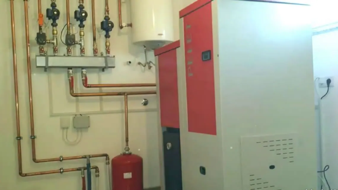
Today, Savo Kusić is focused on wooden windows, wooden-aluminum windows, custom windows, doors and requests for quotation. This text remains as an archive of home installations and is not an offer to design, perform or service a heating system.
Central or apartment heating
If the boiler is located well below the radiators (e.g. in the basement), this is described as central heating; if the radiators and boiler are on the same level, it is apartment heating.
There are two pipeline solutions for central heating. Which will be applied in a given case, it depends primarily on the character of the building (apartment).
System with lower distribution
In the case of a gravity system with a lower layout, the distribution lines with hot water coming from the boiler as well as the collection - return lines with cooled and collected water from the radiator to the boiler are connected to the radiators from the bottom (fig. 1). The distribution and return lines towards the farthest heating element rise evenly so that when filling the lines, all the air is forced out of the pipes. The angle of inclination of the rise should be at least 3-5% (per running meter 3-5 mm). With this system, on each individual connection on the radiator, it should be next to the regulation valve, or. closure, and a separate valve or tap to release the air. When filling the system, all valves should be opened individually to allow air to escape from all places. In these cases, a larger container (bucket) should be placed under the vent faucets and the faucet should be closed only if the water is leaking without air.
In larger plants, vent valves have been replaced by thin pipe vent lines (3/8’’). However, with smaller plants this is not necessary, it would only create unnecessary work and costs. The lower layout can be carried out primarily where the basement extends under the entire apartment, or there is an opportunity to create channels for pipelines without raising the floor (for example, when the building is under construction).
A very important additional element of the heating plant is the expansion vessel (fig. 1, d). The expansion vessel is always the highest point of the plant. The task of the expansion vessel is to receive the excess water that is created due to temperature expansion when the system is heated, to return that water to the system when the system is cooling (when it is not heated). This ensures that the system is constantly charged. In addition to this, the task of the expansion tank is also to remove excess water from the system through the overflow, which is caused by overfilling. The volume of the expansion vessel should be 0,06-0,07 mi part of the entire volume of the plant. Since this kind of calculation is long, we can take the thermal performance of the plant as the basis of the calculation, i.e. for every 1000 kcal/hour, take 2-2,1 liter of the volume of the expansion vessel. For example, for a 15.000 kcal/hour plant, 15 x 2 = 30 liters can be taken. In the case of a system with a lower arrangement, it is advisable to place the expansion vessel in the same room with water (eg bathroom, toilet, kitchen), under the ceiling. In this way, no anti-freeze measures are needed, and the overflow can be simply connected to the sewer.
System with upper distribution
In the case of plants with the upper arrangement (fig. 1, b) the heated water reaches the attic space, through the distribution pipe placed under the ceiling or through the vertical so-called main risers. From the distribution pipe, the water goes down to the heating elements via riser lines, and from the heating elements, using the collecting pipes, which are located under the heating elements, it returns to the boiler. With this solution, the distribution pipes from the farthest heating element to the main riser should have an even rise, and the collecting pipes should have an even fall towards the boiler.

SLIKA 1
The expansion tank should be placed in the attic and should be protected from freezing. This can be solved in the simplest way with a paper cover and insulation material between the vessel and the cover (dry sawdust, straw, rags, etc.). The thickness of the insulation layer should be at least 15 cm. The overflow pipe is placed so that the water flows over the roof into the gutters.
No special vent valves are required for overhead manifold plants. When filling the plant, the water pushes the air in front of it in the expansion line. The system with the upper distribution is usually made where there is no basement under the apartment, and the problem is the placement of the return water at the floor level. Under no circumstances should we place the horizontal distribution network on the ceiling (even if this would be the most favorable solution from an aesthetic point of view), because in that case it would have to be well thermally insulated, and even so, we would have very serious heat losses.
Apartment heating
Apartment heating (fig. 1, c) is a particular form of gravity hot-water heating with upper distribution in which all appliances, fittings and the complete system are located on the same building level. The boiler is usually located in a room that also needs heating, with the expansion vessel beneath the ceiling in the same room.
By comparing heating systems, it can be said that the system with the lower distribution requires the least piping and that this system has the simplest installation. Its disadvantage is that it is more difficult to remove the air from it. The advantage of the system with the upper distribution is that when cooling the pipe, the created effect of circulation and air is not a problem. The disadvantage of this system is that its assembly is more complicated and requires more materials.
Calculation and dimensioning of pipelines
When we have made the choice of the most favorable system for us, we can draw the wiring diagram. It is recommended to make the diagram axonometrically (because it is more transparent) and use different colors for hot water lines and return lines. All changes of direction should be indicated on the drawing, even the so-called level connections and write the corresponding length to each part. Valves should be provided for radiator connections, and shut-off valves only where necessary.
In the final design phase, pipe diameters should be determined for individual parts of the pipeline. To dimension the pipe, first establish the force of circulation of the flow, i.e. the available pressure should be determined. This, as already mentioned, is obtained as the difference of the specific weights of the heated (distributed) and cooled (return) water. The pressure is calculated from the form p = a x h, where p is the available pressure in millimeters of the water column, a - is the difference of specific weights of heated and return water in kp/m3; h - is the effective height, the distance between the middle line of the boiler and the heating element in meters (fig. 2, a).
The cross-section of the pipeline is determined by calculation. It should be sufficient for the circulation force (available pressure) to overcome the losses due to friction in the pipes and due to the change of directions, and for enough water to pass through the heating elements per hour to provide the calculated required heat. For example, a heating element designed to emit 200 kcal/hour should receive at least 100 liters of water per hour.

SLIKA 2
Pipe sizing is carried out by specialists using tables. Picture no. 2, b shows an apartment-heating scheme for a family house. With apartment heating, the effective height is minimal and the available pressure arises almost entirely from cooling in the pipes. The historical text says not to size to the limiting values but always to retain a safety margin. For radiators closer to the boiler, it gives a reserve of 10-15%, because circulation and therefore heat delivery are lower there.
Installation and testing of the system
By calculating the dimensions of the pipe, we have completed the design and have all the necessary data for the construction of the plant. Based on them, we can procure the necessary pipes, fittings, profiles. (Purchasing galvanized pipes would only increase costs unnecessarily.) Pipeline installation can be done in two ways by welding or using threaded fasteners. The welding method is faster and more aesthetically pleasing, but it is more difficult to solve on a DIY basis. Welding requires a machine and can only be used by authorized persons. In addition to this condition, it is necessary that the person performing the work has experience in pipeline work.
When assembling pipelines by the welding process, for changes in direction, the pipes are bent in a hot state. Pipes of a smaller diameter (up to 1“) with some experience can be bent “empty”, while pipes of a larger diameter are bent so that they are filled with sand beforehand. Assembly will be faster if we get pre-bent parts for the pipes of a larger diameter. From these pieces, we can then make other elements (e.g. arc connections).
When assembling pipes with sleeves, as with water pipes, ductile iron elements are used. We mount the elements in the usual way with the insertion of soaked tow between the coils. Due to the threading, this method of assembly requires more work, but also less expertise.
We can start the installation of pipelines after installing the boiler and heating elements. First, the valves should be placed on the heating elements to take them into account when cutting the pipes. The valves attach to the threaded radiator connection with a dutch nut. Asbestos rubber gaskets must be used for sockets with Dutch nut and rim. Leather and hard paper seals are unsatisfactory because they have a short life. Before final assembly, the sealing ring should be oiled. The valves must not be installed in reverse, because their resistance against the flow is much higher. After installing the valve, mark the necessary holes in the walls and ceilings and drill them. We must pay attention to the dimensions of these openings so as not to widen them during assembly.
Pipe installation should start from the boiler connection and first place the main riser and distribution lines, and then connect the heating elements from them. The same should be done with the installation of return and collection lines. When mounting with tube nuts, manifolds, or collection pipes, should be assembled by individual parts of the pipeline, with the necessary connections also being installed. For pipes, which are installed horizontally, the required size and direction of inclination should be controlled with a spirit level. In each place, where the creation of air bags is expected, vent valves should be installed, but making sure that the valve is at the highest point of that sector. Where the pipe crosses the wall, a sleeve must be placed on the pipe during installation, i.e. a piece of pipe longer than the wall at least 10 mm and slightly larger in diameter than the pipe (2-5 mm.) In this way, the pipe will not damage the wall and plaster due to thermal expansion.
The lines, which are placed horizontally, should be fixed every 2-3 m with angle steel supports, and the longer vertical lines with brackets. Fasteners should not be over-tightened to prevent the pipe from loosening the struts or brackets due to expansion. After assembly, once again check in detail the entire network, connections and connections of the pipes to detect possible errors.
After visual control, water control can be performed. For water control, all radiator valves should be opened. To the connection for draining and filling, which is located near the boiler, we connect the water network or a well pump with a rubber hose and fill the system with water. If necessary, the system can also be filled through the vent of the condensation vessel (with a bucket), but filling in this way is very tiring and time-consuming, because the air must leave the system against the flow of incoming water.
During charging, you should continuously monitor the system and if it starts to leak somewhere, stop charging immediately and continue after fixing the error. We must also not forget to open the exhaust valves (where there are any) during the filling of the system. The system is filled when the water comes out of the condensing vessel through the overflow and when we create vent valves so that water flows continuously through them. If there are no leaks anywhere, then we can prepare for the test heating.
Trial heating and maintenance
We first light the fire in the boiler by filling the furnace with newspapers (the draft regulator should be opened). This way we will overheat the boiler and check the draft. If all is well, then we can fire the stove regularly. For test heating, wood should be used if possible, because the plant will heat up this way the fastest. A few minutes after ignition, we should feel the flow of hot water in the lines, and after 15-40 minutes, depending on the size of the plant and the intensity of the heating, the return line should also be heated, giving a sign that the water has completed complete circulation.
When the water flow has started in all radiators, the water should be heated to a temperature of 90°C. In the case of a system with a lower distribution, all the exhaust valves should be opened in turn for a few seconds and this should be repeated several times during the test heating. In this way, we will achieve that the gases, which are separated from the water due to the temperature, can freely leave the system. Once we have made sure that the plant is working flawlessly, we let the fire go out and let the plant cool down, so that we can do the finishing touches. First we need to repair the walls where we drilled and then paint the pipe network. Painting should be done after cleaning and degreasing in three layers (see instructions when buying a special paint). Between the application of individual layers, the mesh should be allowed to dry for at least 24 hour, even before applying the last layer or more, because the enamel is with a nitro base and if the base layer is not dry enough, it will create wrinkles.
Water should be heated only to a degree that will ensure the desired temperature of the rooms we are heating. The water temperature depends on the outside temperature, and we can regulate the room temperature by gradually adjusting the radiator valve.
The water level in the expansion vessel should be controlled at least once a month or to supplement. We release water from the system only in very justified cases.
This is a historical text, and the listed units, formulas, materials and procedures are not a project, calculation, assembly instructions or commissioning of a modern system. Do not use sealants or other products that contain asbestos. Boiler, chimney, air supply, fire and carbon monoxide protection, expansion, safety devices, pressure, temperature, materials, flushing and testing must be determined and checked by an authorized designer and contractor according to current regulations and manufacturer’s instructions. Improper filling, welding, burning or sealing of the system can cause fire, poisoning, burns, leakage or dangerous pressure build-up.