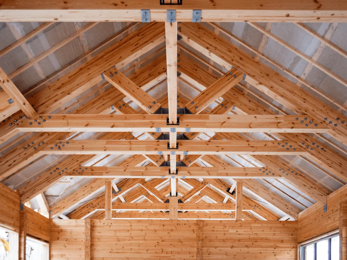
For greater loads and spans, calculations produce beam cross-sections that are difficult to obtain in the required lengths. In such cases, built-up structures must be used. The structures described under 1 and 2 are entirely products of craftsmanship. The use of modern fasteners is entirely appropriate.
1. Beam joined with shear keys
Two beams, and sometimes three beams in bridge construction, are placed one on top of another and then connected to each other with shear keys and bolts. The extent to which such a cross-section reaches the load-bearing capacity of a corresponding solid cross-section depends on the effectiveness of the keys, the moisture level of the timber and the quality of workmanship. This will never be achieved completely. According to the DIN standard, the section modulus for two beams is W=0.85 bh__2_/6_, and for three beams W=0.7 bh__2_/6_. For bridges, these coefficients are reduced to 0.8 and 0.6 respectively. When calculating deflection, take the moment of inertia for two beams as I=0.6 bh__3_/12_, and for three beams as I=0.3 bh__3_/12_. If the wood shrinks, the bolts should be tightened accordingly.

Figure 1: Beam joined with shear keys, used as a girder in a floor structure.
For rectangular carpenter-made keys, which are always made of oak, the most suitable notch depth is 1/8 to 1/10 of the height of the individual beams; the fibres of the key and the fibres of the beams must run in the same direction.
To prevent downward deflection, the keyed beam is given an upward camber, or rise, towards the middle of the span before final assembly. The beams are connected with bolts, while the recesses for the keys are cut in one operation with a chain mortising machine. Figure 1 shows a keyed beam used as a girder in a floor structure. Keyed beams are made for spans of up to 15 m.
Keyed beams should be used only exceptionally because all types, in addition to their relatively low load-bearing capacity, require considerable labour and material. It is important that deformation caused by loading be as small as possible.
2. Suspended, supported and combined systems
If the normal cross-section of a beam is insufficient and there is enough space below or above it in its plane, for example on roof frames, bridges or scaffolding, a suspended system, a supported system or a combination of the two can be installed. Depending on the number of points at which suspension or support takes place, there are single and double suspended systems and single and double supported systems. In calculating a single suspended system (Fig. 2), it is assumed that the post or vertical placed halfway across the span and the two inclined members transfer half of the uniformly distributed load acting on the horizontal tie to each support. Figure 3 shows the connection between the vertical and the tie. Figure 4 shows a double suspended system forming a load-bearing roof structure (left half: roof with struts; right half: roof with purlins).

Figures 2–5: Single and double suspended systems, the vertical-to-tie connection and the joint of inclined member, post and strut.
The horizontal member between two verticals is called a strut. Figure 5 shows the joint at which the inclined member, post and strut meet; a gusset plate is fitted for heavy loads. In a supported system, the load-bearing structure is below the beam that is supported at one point (Fig. 6) or two points (Fig. 7). In this case, the horizontal component, or thrust, must be taken by the support. To strengthen the tie, the strut in Figure 7 is connected to it with keys and bolts. Figure 8 shows a combined suspended and supported system. To allow the inclined members to be made without splicing, the tie must be doubled.

Figures 6–8: Support at one and two points and a combined suspended and supported system.
3. Solid-web trusses
Beam trusses
Solid beams modelled on the I-sections of steel structures occur as keyed, glued or nail-laminated beams. The upper span limit is 15 m. As with steel structures, the structural depth should be 1/8 to 1/12 of the span. The simplest web is a vertically placed plank connected to the flanges with keys and bolts (Fig. 9). Stiffening verticals made from planed timber and placed between the flanges should be avoided in these girders because, when the timber shrinks, they prevent a reduction in depth and can cause the web to tear away.

Figure 9: The simplest form of web in a solid beam truss.
Figure 10 shows a simple beam with a span of 14.04 m. Joints in the web are covered with glued pieces of plywood. The webs are secured against buckling by stiffeners made of planed beams. The required pressure for gluing the elements was provided by bolts, which remained in the structure for safety after the adhesive had hardened. The web consists of two layers of boards, 24–40 mm thick, laid across each other and nailed together. Keys and bolts, or nails, are used to connect most elements. If the flanges consist of several boards, their movement relative to the web increases the farther the boards are from the web. The compressed flange must be checked for buckling. Figure 11 shows an example according to Russian standards.

Figure 10: Simple beam with a span of 14.04 m.

Figure 11: Example of a beam truss according to Russian standards.
Hollow girders have lower stiffness (Fig. 12). The upper and lower flanges are each formed by one planed beam, which can easily be given the required camber. It is useful to install an inclined compression member at the support, bearing against the lower and upper flange through a notch; although not by much, this increases the stiffness of the beam.

Figure 12: Hollow girder.
Arch trusses
Figure 13 shows a truss for a salt-storage warehouse in the Netherlands. The span is 54 m and the truss spacing is 5.4 m. Prestress produced by bending the boards being glued has no appreciable effect on the load-bearing capacity of the structure. It is not necessary to reduce the moment of inertia or section modulus for glued cross-sections.

Figure 13: Arch truss for a salt-storage warehouse in the Netherlands.
Figure 14 shows a light three-hinged glued frame girder. The web is made of planks 18 cm to 20 cm wide and 5 cm thick which, after drying, were glued to each other and to the lower and upper flanges with Kaurit adhesive and a yellow cold-curing additive.

Figure 14: Light three-hinged frame girder made by gluing.
Nailed arch trusses whose web consists of two layers of boards crossed at right angles, with several vertical boards arranged in the shape of the arch nailed on as flanges, are very economical. Relatively weak and short timber can be used even for the greatest spans.
4. Lattice trusses
Modern timber lattice structures mostly follow the forms and systems of steel structures, although these are not always rational for timber construction. Timber structures are designed so that secondary forces at connections are as small as possible. Secondary stresses do not have the same significance as in steel structures. Members with smaller forces often need not be connected concentrically, especially if this simplifies construction. Lattice structures are more economical than solid girders when sufficient structural depth is available. However, they make greater demands on the carpenter and the material.
The bottom chord of beam trusses is usually horizontal; during fabrication it is given a camber measured so that it does not deflect downward under full load. The camber depends on the external means, timber moisture and structural depth of the truss. It is better to provide a little too much camber than too little. The top chord usually runs parallel to the roof covering.
If the pitch is too small, below 6%, a low structural depth and flexible joints may create reverse falls near the supports, with harmful consequences. The slope of the statically effective top-chord member at the support should not be less than 1:3.
Parallel-chord trusses
The well-known Howe truss is still used today (Fig. 15). The diagonals are arranged to take compression under full load, while the verticals are in tension. The verticals are circular steel rods with nuts at both ends (Fig. 15, right). If the truss deflects downward because of timber shrinkage or inaccurate workmanship, the nuts can be tightened later. For smaller spans or lighter loads, the verticals may also be made as pairs of timbers (Fig. 15, left). As with solid girders, the recommended structural depth is 1/8 to 1/12 of the span; for larger spans and heavier loading, up to 1/6 is used.

Figure 15: Howe parallel-chord truss.
Mono-pitch roof trusses
Figures 16 and 17 show mono-pitch truss systems for small and medium spans and light loads.

Figures 16–20: Systems of mono-pitch and triangular roof trusses.

Figure 21: Details of a lattice truss.
Triangular trusses
Triangular trusses (Figs. 18 to 22) for small and medium spans are the most economical and widespread timber trusses. The greatest chord forces do not occur at mid-span but at the supports. Because the web members are subject only to tension or compression, even under asymmetrical loading, without alternating stresses, the construction of joints is greatly simplified, particularly in timber structures. Figure 22 shows a truss for the municipal hall in Holzminden. For larger spans, triangular trusses with raised eaves are made (Fig. 23).

Figures 22 and 23: Triangular truss for a municipal hall and a truss with raised eaves.
Mansard trusses
Mansard trusses (Figs. 24 to 26) for spans from 15 m to 35 m have proved very economical. System depths of 1/8 to 1/6 of the span are recommended. Corrugated asbestos-fibre sheets and roofing papers may be used for covering. A minimum pitch of 6% should also be adopted for the gently sloping part of the roof. Figure 26 shows the system line of a truss for the München-Ost workers’ facilities, together with several important joints of the Kübler system. The span is 26.5 m and the truss spacing is 7 m.

Figures 24 and 25: Mansard trusses.

Figure 26: System line and joints of a mansard truss for München-Ost.
Parabolic and arch trusses
For roofs with high dead weight and low pitch, and therefore small surfaces exposed to wind, with approximately uniformly distributed snow load, it is rational to adapt the form of the truss to the funicular line. The web members of parabolic trusses carry no forces under uniformly distributed loading. Their task is to take accidental irregularities in loading and prevent buckling of the top chord in the plane of the truss. Web members must be connected so that they can take both tension and compression. The upper edge is shaped into an arch by sawing (Fig. 27). Figure 28 shows the system line and three characteristic truss joints.

Figure 27: Parabolic truss with its upper edge sawn to an arch.

Figure 28: System line and characteristic truss joints.
If, for very large spans, only the roof-covering support is made as a lattice girder (Fig. 29), the lower chord, which takes compression, must be braced against the purlins. Because of the varying pitch, unsanded roofing felt is suitable for covering the roof. A uniform roof pitch can also be achieved either with raised rafters supported above the eaves and ridge, or by a wall above the eaves, that is, by installing a gable roof with the gentlest possible slope.
Two-hinged and three-hinged trusses
Two-hinged frames are shown in Figures 30 and 31. Constructing rigid corner joints presents certain difficulties, most easily overcome by using gusset plates glued with synthetic resin. Alternating stresses occur in the web members, making the joints awkward to design. Figure 32 shows a two-hinged lattice frame for a boat shelter, with truss spacing of 5.6 m. Figure 33 shows a three-hinged truss. True hinges are generally unnecessary; a certain degree of movement is sufficient. Three-hinged trusses are used primarily for large and the largest spans because they are economical for this purpose and can be technically well executed.

Figures 29 and 30: Lattice roof-covering girder and two-hinged frame.

Figures 31 and 33: Two-hinged frame and three-hinged truss.

Figure 32: Two-hinged lattice frame for a boat shelter.
Multi-bay halls
Figures 34, 35 and 36 show practical types of multi-bay halls. Figure 36 shows the truss of the ceremonial hall of a choral society in Vienna. Ring-type shear connectors were used for the joints.

Figures 34 and 35: Practical types of multi-bay halls.

Figure 36: Truss of the ceremonial hall of a choral society in Vienna.
5. Towers, scaffolding and stands
As a building material, wood is suitable for observation and viewing towers, church towers and towers for industrial facilities. The stability of permanent structures is generally achieved by fixing the columns into the foundations. Structures intended for temporary purposes are often secured with steel cables stretched in at least three directions. The plan is usually square or rectangular. Triangular plans may sometimes be economical. Particular care should be taken to ensure that water or dirt does not collect in the joints of unclad towers and that air can circulate around all parts. Only impregnated timber should be used for permanent structures. Impregnation fully achieves its purpose only if carried out after the timber is cut to shape but before assembly. Round timber is recommended for columns even though the joints are more difficult to make.

Figure 37: Timber stand in Leipzig.
Timber is also useful for scaffolding and stands. Figure 37 shows a stand in Leipzig. Alligator toothed-ring connectors were used for the external joints. If stands are intended only for temporary use, they are never covered. Nevertheless, design must be carried out with the greatest care and, above all, the necessary longitudinal and transverse bracing must be installed. To allow the timber to be reused after dismantling, the joints should be designed so that damage is kept to a minimum.
6. Bridges
Alongside stone, wood formerly played an important role in bridge construction. Conditions concerning the durability of structures have changed significantly. Because of the continual increase in axle loads and dynamic loads, this field of construction has been almost completely lost to timber structures. Timber bridges are not in use today, but the following text describes how they were constructed and used in the past.
Only timber of quality class II or I may be used for bridges; when installed, the timber must at least be semi-dry and should be installed so that it can continue to dry. For this purpose, impregnation and protective coatings, which in a given case must be applied after processing but before assembly, are not sufficient in themselves.
Nailed joints are permitted for bridges if moisture can be prevented from penetrating between the nailed timber elements and if the nails can thereby be protected against failure due to rusting. Glued joints are permitted only if a synthetic-resin adhesive that is fully resistant to moisture is used.

Figure 38: Cross-section through the deck of the temporary bridge over the Weser in Höxter.
Combined structural systems were mostly used for temporary bridges: steel I-sections served as the main girders, while the remaining parts of the superstructure and substructure consisted of timber. Figure 38 shows a cross-section through the deck of the temporary bridge over the Weser in Höxter. Bridges may be without longitudinal girders, and sometimes without cross-girders, depending on the type and purpose of the bridge. In that case, the deck rests directly on the main girders. Many such bridges were built for pedestrian traffic. Figure 39 shows a protective bridge beneath a cableway.

Figure 39: Protective bridge beneath a cableway.
Related topics
For more about the material, see Timber, and for how the company works, see Production. For the use of wood in joinery, see wooden windows and wood-aluminium windows.