
Important technical note: This is an archival educational text, not a current design specification, structural calculation, proof of load-bearing capacity, or manufacturing and assembly instruction. The design of halls, domes, frames, tall masts, towers, mining structures and tubular structures requires a qualified designer, geotechnical and other relevant design data, actual actions, checks for stability, fatigue, fire and corrosion, and the applicable regulations and standards.
The design and construction of steel structures is not part of the current public offer of Savo Kusić. Today’s production focus consists of wooden windows, wood-aluminum windows and custom doors.
Halls
1. Domes. There are domes in which all the rods lie on the surface of the dome, which form spatial systems, while in others, the domes are formed by the radial arrangement of individual fasteners. Domes that are spatial grids can have the following shapes:
- Schwedler’s domes, where the ribs are radial and connected to each other by horizontal beams (fig. 1)
- Mesh domes, whose surface consists of a network of triangles, without radial ribs, but with encompassing bands of the same number of angles (fig. 2). If such a dome is based on a regular polygon with an even number of sides, the system is unstable and unusable without special stabilization.
- Zimmerman domes, where there are, similar to Schwedler and mesh domes, horizontal rings, but the number of angles on the rings gradually decreases as the height of the rings increases. The advantage of Zimmerman’s domes compared to Schwedler’s and mesh domes is that only vertical forces occur at the corners of the lower part, while horizontal forces from the wind are received by the middle of the walls in the longitudinal direction (fig. 3).
- Slick or plate domes, in which, as in mesh domes, all individual surfaces are triangular, while the method of support is similar to that of Zimmerman domes (fig. 4).
- Tent roofs, where the ribs are rectilinear (fig. 5).
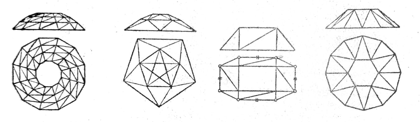
Figs. 1, 2, 3 and 4, respectively

Fig. 5
2. Sports halls. The construction of sports halls is determined by the shape of the arena and the seating arrangement. Pillars are avoided, so that observers have a clear view of the entire interior.
3. Exhibition halls. In the case of exhibition halls, a rectangular base is used, so that the arrangement of fasteners is the simplest. Sometimes internal columns are also provided, but there is greater freedom in the distribution of space if there are no columns in the hall.
4. Workshop halls. The project of a steel structure for a workshop hall is created by the cooperation of an operating expert, a crane designer and a steel structure designer. The drive specialist determines the dimensions of the base and the spacing of the columns according to the layout of the machines and the work plan. He also determines the filling of the walls, the roof covering as well as the foundation methods, according to the opinion of construction experts. The crane designer determines the own weights of the trolleys and cranes, the wheel spacings and the most unfavorable wheel pressures. Based on the data of the operating expert and the crane designer, the steel structure designer determines the supporting structure of the hall. The crane supports should be as stiff as possible and, if necessary, designed with an overhang, so that when a heavily loaded crane passes through, the crane rail has a horizontal position, and thus a relatively small crane motor can be chosen.
5, Saw-shaped halls. Saw-shaped halls are generally built when uniform lighting is required and the direct penetration of sunlight into the interior of the hall is to be avoided. This is especially important in production and warehouse halls of the textile industry. The sawn roofs have a 60o to 90o glazed surface, while the slope of the massive surface is 30o. The glazed surface is placed on the side where there is no sun, that is, towards the north. When designing sawn roofs, one should take into account a whole series of issues, the solution of which is the authoritative opinion of the investor, namely: the roof covering can be made of light prefabricated panels or tiles on a wooden base, sawn fasteners can be lattices (Fig. 6), frames with three joints (fig. 7), resp. frames on two joints with tension (sl 8). The lattice solution has the least weight, but they have the disadvantage that the lattice sticks, e.g. in the textile industry, they retain wool lint. If the aim is to have as few columns as possible in the interior of the building, a solution with large-span grids can be applied in both roof planes, which mutually support each other and are supported at the ends on grid supports.
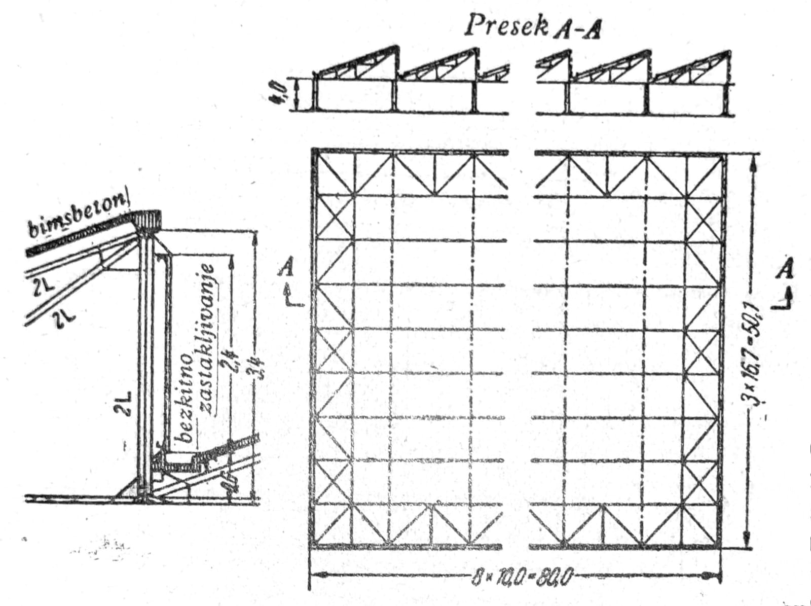
Fig. 6
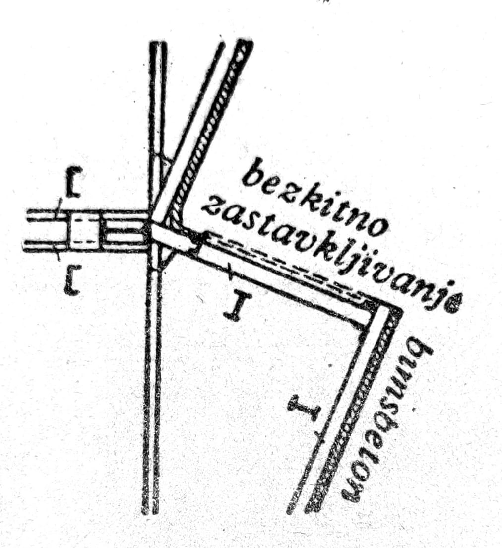
Fig. 7
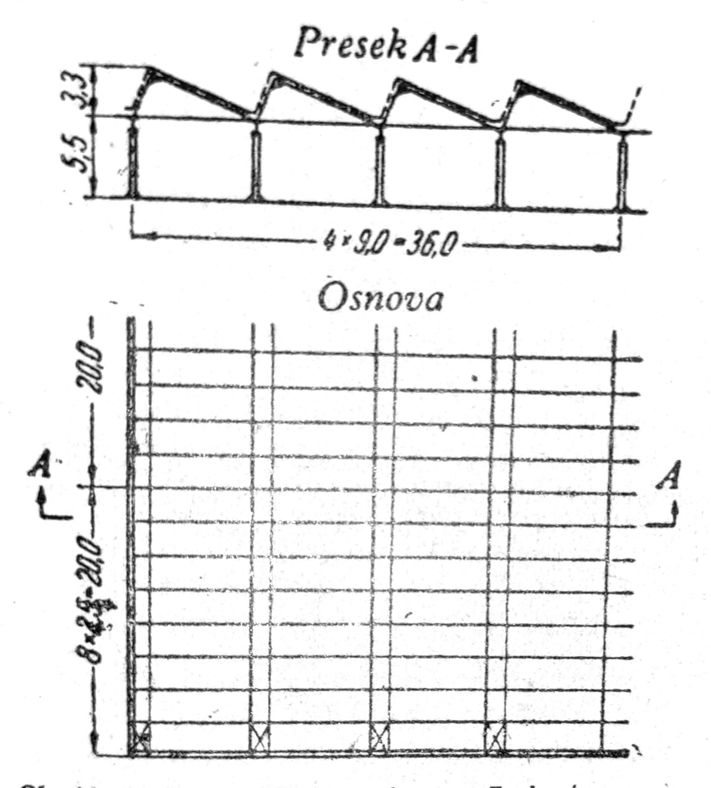
Fig. 8
Slipway structures
The constructions over the slipway carry hanging revolving cranes. They are used for the rough assembly of vessels for sea and river traffic. High slewing cranes and cable cranes compete with these constructions. In fig. 9 shows the structure on the slipway of Nordseewerke Emden. Weight 3000 t, built 1912.
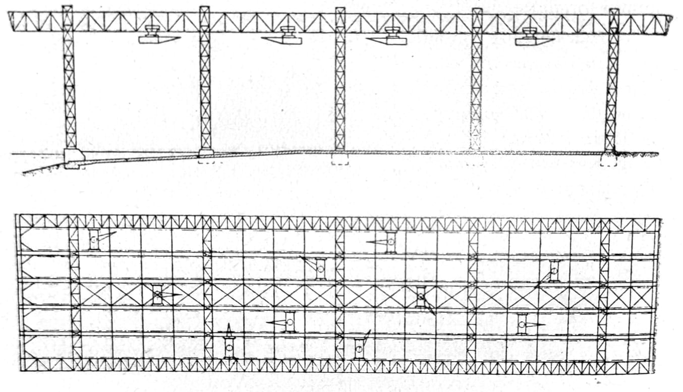
Fig. 9
Steel-framed structures
A steel skeleton structure is a structure with several floors, whose columns, supports and girders made of steel themselves transfer to the foundation the load from the own weight of other materials, as well as useful loads. External and internal walls serve only to enclose the space. In addition to its own weight and useful load, the steel skeleton also receives wind pressure on the building, in the longitudinal and transverse directions.
Skeletal constructions generally have such a shape that the columns and beams form transverse frames. These frames have roughly the same distance between them in the longitudinal direction of the building and are connected by longitudinal supports. Frames can have two or three posts. The connections of the substructure to the columns can be rigid or hinged.
In order to stiffen the building longitudinally, vertical joints are placed in fields without windows (fig. 10), or all the supports of the external walls are rigidly connected to the columns so that a frame construction with numerous nodes is created (fig. 11).

Fig. 10

Fig. 11
The choice of materials for ceilings, interior and exterior walls is of decisive importance for the economy and expediency of the solution. Those materials must have a thermal and sound insulating effect, they must be light and resistant to atmospheric influences, they must protect steel walls from fire, rusting and condensation. Ceilings are made of concrete with plain or crossed reinforcement or of prefabricated concrete parts.
The possibility of applying steel skeleton constructions is very diverse. They are used in the construction of high-rise and commercial buildings, hotels and many industrial plants, and have many advantages compared to other construction methods. The high strength of the steel leads to relatively small dimensions of the supporting elements. Since the walls here do not participate in carrying the load, they can be of equal thickness on all floors. The time required for the construction of the steel skeleton is short, assembly can be done in any weather. Changes to the structure can be easily implemented during assembly and even after taking over the building, without jeopardizing the safety of the building. Ground subsidence can be easily equalized by raising columns without interrupting the operation of the building itself.
In such constructions, light materials are used for ceilings and walls, and the supporting structure itself is also light, so the total own weight of the building is relatively small. As a result, the cost of funding is low. They can be easily dismantled, whereby individual steel parts can be partially reused.
Tall masts and towers
Tall columns and towers are tall and slender structures, relatively lightly loaded, for which steel is a particularly suitable material.
1. Lighting poles. For the sake of uniform illumination of the largest possible areas, especially in the area of railway facilities and mines, poles with a height of 25 up to 40m are erected. At the top there is a platform on which the lighting installations are placed. In order to facilitate the repair of those installations, climbers are foreseen (fig. 12), Corner belts, diagonals and horizontals are made of angles. The calculation is made as for constructions in the building industry.

Fig. 12
2. Poles for the tram network. Considering the way of tensioning the supporting rope, equal resistance to bending is required in relation to all horizontal axes. Depending on the height, the sheet thickness ranges from 8 to 10 mm.
3. Poles for the electric railway network. They have a height of 8 to 16 m. The height depends on the span, and thus on the arrow of the supporting rope, which can lie vertically or obliquely to the conductor (fig. 12). The section, which is rectangular at the bottom and square at the top, should be as small as possible. It is useful to tie the diagonals from the corners directly to the belts, without knotted sheets. Each corner belt has a bearing plate at the lower end, and the entire column rests on a common foundation for all four belts. The column is attached to the foundation with concrete anchor bolts.
4. Power line poles. In the case of important high-voltage transmission lines, the poles are made almost exclusively of steel. Their height depends on the free span, arrangement of consoles, materials and permitted voltages, conductors and protective rope on the pole, as well as on load conditions. The number of alternating current systems that are transmitted over the poles is also of influence. Depending on the purpose, the following types of poles are distinguished: bearing poles for carrying conductors in the direction (fig. 13), corner poles with breaking points of the route for receiving horizontal components of the conductor, tension poles (fig. 13), connecting or dividing poles that are used for connection, or division of conductors in various directions.

Fig. 13
The column almost always has a square section and is made of several parts in height. Belts and diagonals are made from angles. In order to increase the buckling strength, the belts are partially filled with concrete after assembly. The connection of diagonals and belts is made, if it is structurally possible, without nodal sheets. Smaller columns, especially supporting columns, are anchored to wooden sleepers that are buried 3 m. High columns are placed exclusively on one concrete block foundation.
Mining facilities
Specific technical terms are used for surface mining facilities; the most important are explained in Fig. 14. The main part of the mine headframe is the guide tower. Its height depends on the elevation of the loading platform above the ground, the length of the cage, the length of the overwind path, the height of the buffer and the fall distance between the buffer and the catches.

Fig. 14.1.

Fig. 14.2.
Over the years, several forms of headframe developed according to the position of the winding engine relative to the tower. With a single winding system, where one cage rises while the other descends, the cages may hang side by side as viewed from the winding engine. The two sheaves can then be positioned beside each other on the same platform, producing a single-level headframe. Figure 15 shows a solution with four sheaves arranged side by side.

Fig. 15
If the cages hang one behind the other, the sheaves must be arranged one above the other, giving a two-level headframe (Fig. 16). In a double winding system, when four cages lie side by side as viewed from the winding engine, all four sheaves may be placed beside each other on a single-level headframe (Fig. 15).
If, however, looking from the machine, four baskets are placed one behind the other, one machine must be placed on the opposite sides of the tower, and the tower is solved as a two-story structure with a spread lower part (fig. 17). Only when there is not enough space near the shaft to place the engine house next to the tower, the drive engine is placed on the tower itself.
In addition to headframes, mine surface facilities may include shaft-side halls and coal-preparation plants. Designing these facilities requires cooperation between the steel-structure designer and the equipment supplier. In principle, they do not differ from other steel structures, except that the structure must be continually adapted to the mechanical equipment. In a workshop hall, for example, all frames may be assumed to be identical; this is rarely the case in a mine hall or coal washery.

Fig. 16

Fig. 17
Tubular structures
A tube is the most favourable cross-section for a compression member supported equally in all directions. It also permits the smallest wall thickness. In other sections, wall thickness is more limited by local instability than in a cylindrical tube. Tubes are particularly resistant to torsional buckling compared with other sections used in steel structures. Alongside these structural advantages, tubes have an unfavourable form for resisting bending moments and thicker tubes are difficult to connect at an angle.
Pipes can be made either from bent sheets with a welded longitudinal seam, or as seamless rolls. In both cases, the price of the pipe is higher than the price of the profile, considering the difficulties in manufacturing. For these reasons, pipe constructions are competitive only with a corresponding reduction in material weight. Pipes are especially used as pillars of buildings, if they are loaded only with normal forces. Pipes are also used for pillars of underpasses and underground structures. Now they are often used to make scaffolding. In order to prevent internal corrosion, all fittings and connections, as well as the end pipes, should be completely sealed.
Application Note: Historical examples, dimensions, typologies and claims of system economy or convenience must not be used as a substitute for current standards, site conditions, technical characteristics of materials and equipment or expert verification of specific construction.