The load-bearing capacity of a member is limited in almost all cases by buckling of the compressed flange. This occurs only after the yield limit has been reached, following equalization of stress throughout the compressed leg. Only with strong lateral restraint can the permissible edge stress be increased into the range of structural steel strengthening. In assessing load-bearing capacity, the actual stress distribution must be taken into account. Assuming a linear stress distribution would underestimate the load-bearing capacity. Instability phenomena should be examined in particular.
Deduction of holes in beams loaded in bending
On the tension side of the beam, section weakening occurs as in tension members (splitting of the tension flange along the weakened section). The same rules apply to avoiding holes in this sense as for a tension member.
Since the holes filled with rivets on the compressed side of the beam have very little effect on the distribution of stresses and strains, and the load-bearing capacity is mostly limited by lateral buckling of the compressed flange, the extent of the cross-section weakening in beams with symmetrical sections does not significantly affect the load-bearing capacity. Therefore, F. Hartmann had already raised the question of whether it is necessary at all to take weakening by holes into account in symmetrical beams. In asymmetrical sections (the compressed side stronger), the deduction for holes on the tension side of the beam can become decisive for the load-bearing capacity. Under frequently repeated loading, the holes have a significant effect, even when they are located at a greater distance from the edge fibers.
Today, gross and net cross-sections are used in calculating the load-bearing capacity of a section in bending (along with other relevant failure modes). Failure by gross section occurs in the part of the section that is not weakened by holes. Failure by net section occurs in the section weakened by holes, and the area taken into account is the gross area reduced by the area of all openings.
Nails at the neck and in the head
In bending, in addition to normal stresses, shear stresses also occur; in members with parallel flanges they are proportional to the transverse force Q. In composite cross-sections, the rivets connecting the individual rolled profiles take up the shear stresses in the contact surfaces between them. The distribution of the shear force T in the web is parabolic, and in the flanges it is almost linear. In members with heavy flanges, T in the web differs only slightly from the average value Tm, which is often sufficient for a first estimate.

Fig. 1
The rivets in the head (fig. 1b) must together take up the force of the gusset TK < TH. The gusset force between individual flange laminations is even smaller and in the case shown in fig. 1c is distributed among a larger number of rivets.
Extension of a beam
Longitudinal extension of the vertical plate is required when the plate height is greater than the widths of the available plate sheets. It may also be necessary for reasons of fabrication and transport. The splice plates and rivets in the longitudinal extension of one girder must carry the same force TL that the unspliced plate would have in the longitudinal joint. Since the weakening due to holes in the splice plate is the same as in the vertical plate, the thickness of the splice plate must be greater than or equal to the thickness of the web.

Fig. 2 - Longitudinal extension of the vertical sheet metal
The transverse splice under bending load can be covered in various ways by cover plates. Fig. 3 shows several possibilities of shop splice, in which only the vertical plate is spliced. If the cover plates are only between the flange angles (fig. 3a), strips of the vertical plate remain uncovered below the flange angles. Then the angles and rivets in the area of the vertical-plate splice are much more heavily loaded, so this type of splice should be limited to less important connections with small forces. A fully covered splice should always be preferred. Special cover plates on the vertical legs of the angles take up the longitudinal stresses of this strip, but participate only slightly in carrying the transverse force. Some improvement in this respect is shown in fig. 3c. For large forces, cover plates over the full height of the vertical plate should be used (fig. 3d), which implies that the flange angles should be interrupted. The cover plates take on the thickness of the angle leg; for large angle thicknesses, packing plates are used for leveling in order to save unnecessary cover-plate thickness.

Fig. 3 - Transverse splice (shop-made) of a vertical sheet
Vertical sheet splice under transverse shear load: The member at the splice is loaded only by Q (M = 0). For a splice with equal rivet spacing (fig. 4), it should be assumed that the forces in the rivets NiQ approximately correspond to the corresponding element of area e*t of the splice joint, i.e. that the forces in the rivets are distributed in the same way as the shear stresses over the height of the member, NiQ = e*t*τi = e*Ti. However, when dimensioning, a uniform distribution over all n rivets is assumed: NiQ = Q/n.
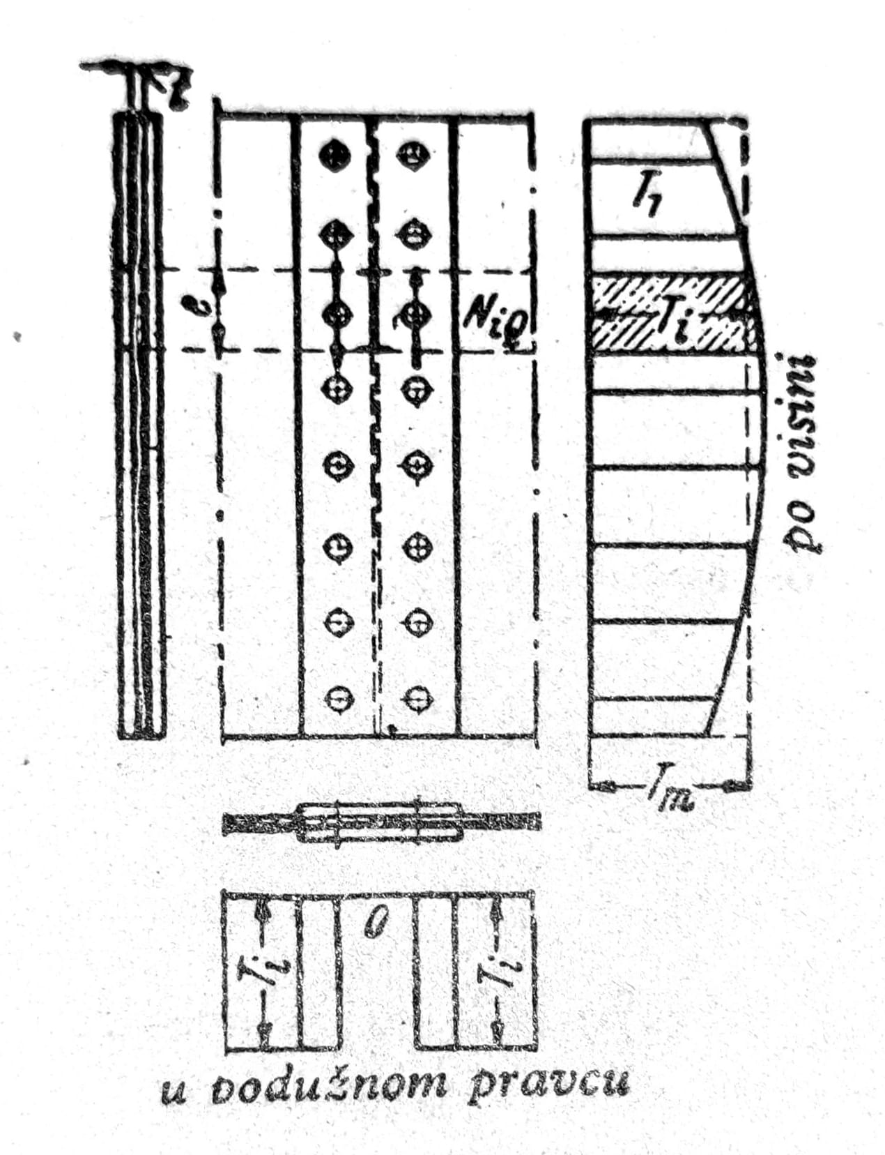
Fig. 4 - Extension of the vertical plate with shear force distribution
Fig. 5 shows a workshop extension of a vertical sheet (the horizontal angles and lamellae are extended elsewhere).

Fig. 5
Bending with axial force: Beams simultaneously subjected to bending moments and normal forces are designed according to the same principles and under the assumption of a straight-line stress distribution. With full deduction of rivets in both flanges, the net section and the position of the neutral axis do not depend on the loading case, so the stresses from M and N can simply be added. The load on the rivets in the splice is obtained by superposition of forces from the partial loading cases M, respectively N.
Support and connection of the beam
Here only the most common of the numerous solutions will be considered. In assessment, one should always take into account the additional forces that arise from deviations from more or less idealized strength calculations.
Simple support of one beam on the top flange of another structural element is used when a large structural depth is available. The normal case is a rigid connection with rivets or bolts. Fig. 6 shows the normal support of continuous I-purlins in building construction, which likewise avoids drilling in narrow I-flanges. In a given case, the beams must be secured against overturning as well as against transverse forces (fig. 7 and 8). In bridge construction, beams are often paired (fig. 9); fixed support of a longitudinal beam on a transverse beam (fig. 10). For greater support reactions, the beams should be stiffened with fitted angles or welded-on profiles (fig. 8 to 10). In composite beams, the load should be transferred into the web.
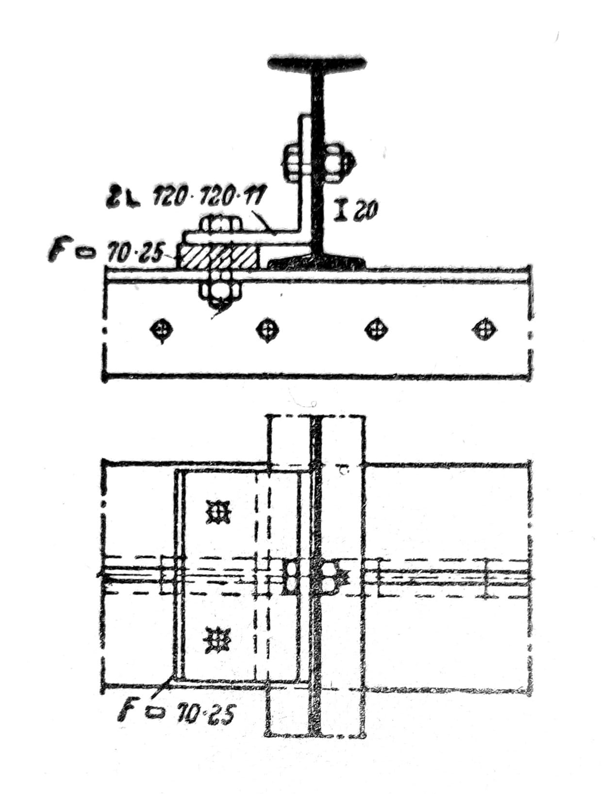
Fig. 6 - Fastening of rafters
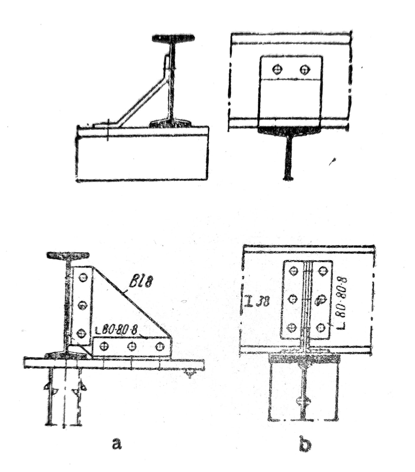
Fig. 7 and 8
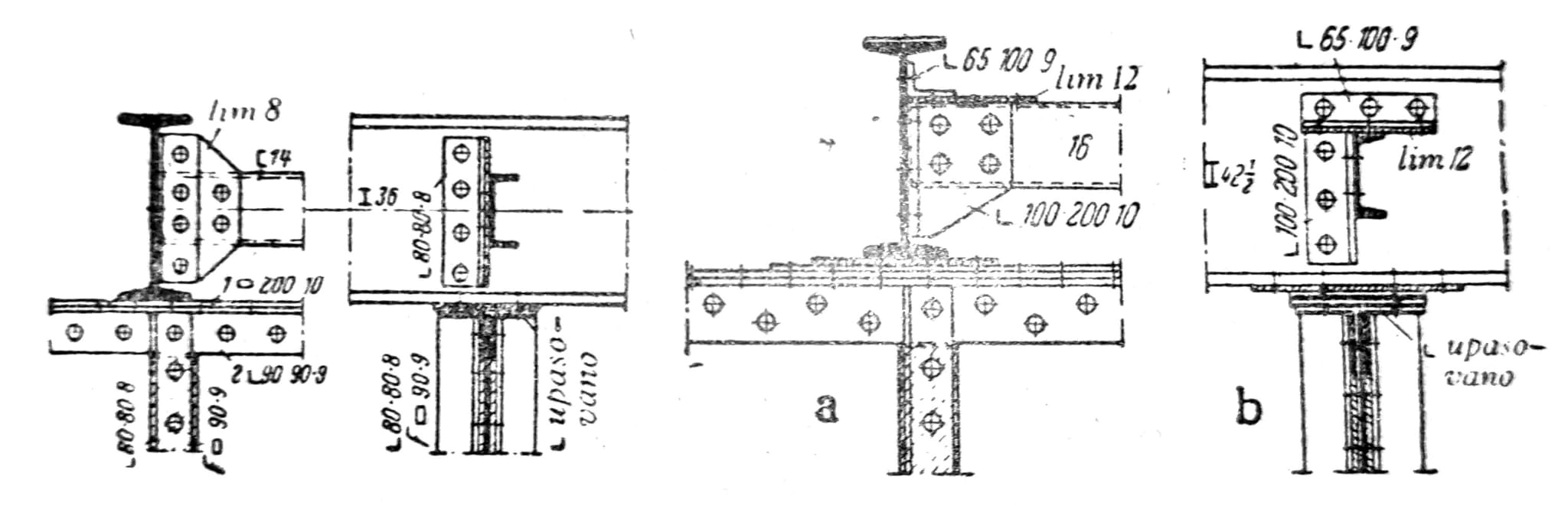
Fig. 9 and 10
Flange connection: In fig. 11 and 12 are shown I-beam connections used in building construction as standard connections. The cut-out receives a large rounding in order to avoid cracking of the beam web. The elastic restraint of the flange connection brings a certain increase in load-bearing capacity. The deformations described are, however, harmless under predominantly steady loading, such as in older bridges.

Fig. 11. - Standard connections of an I-beam with a perpendicular end section
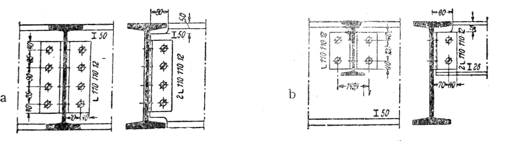
Fig. 12 - Standard joints with cut ends of I-beams
Rigid bending connections are used when a connection without angular change is required (continuous girders, rigid frame corners) or when there is a danger of failure due to fatigue under variable loading, especially in railway bridges. Continuity plates, rigid bending joints, rigid bending corners, and frame corners may be used.
- Continuity plates – If members lying in the same plane are to be connected, both upper chords are joined with a plate or continuity strap. This relieves the fasteners of tensile forces and avoids large deformations.

Fig. 13 - Connection with continuity lamella

Fig. 14 - Connection of longitudinal girders of a) a highway bridge; b) a railway bridge
- Rigid bending connections – This type of connection is found on solid cantilevers of pedestrian walkways on road bridges. For smaller moments, their vertical plate is connected only two-sided between the angles stiffening the main girder. The introduced moment is distributed through the stiffening over the entire height of the main girder, i.e. it is introduced into its flanges as a couple of forces.
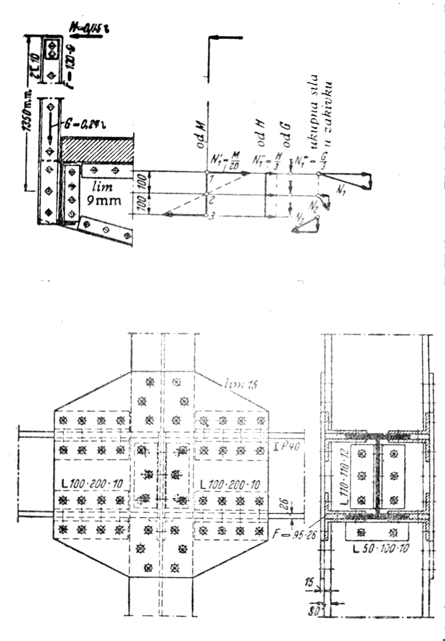
Figs. 15 and 16
- Angles rigid in bending – Angles rigid in bending between columns and beams in building construction should be designed so that the angle remains unchanged and no local stress exceedances occur. Reliable connections at the corners are achieved, for example, according to fig. 16 when wing plates are used, or according to fig. 100 when the moment of fixity in the column flanges is taken as a couple of forces.
- Frame corners – On polygonal frames, the joint can be made at the point of bend if the angle difference is small; the joined bars are covered with straps as tensioned and compressed bars. Torsional forces are concentrated at the bend point and must be absorbed by stiffeners. In fig. 101 note the difference in joint covering and stiffening, depending on the sense of the bending moment and deflecting forces. In the case of large forces and a considerable angle difference, the joint is avoided in the highly curved part of the frame. Joints near the frame corners allow a better structural form and facilitate fabrication. Examples with riveted universal joints on both sides of the point of bend are given in fig. 102a and fig. 102b, in which the corner consists of a welded part. In fig. 103 shows the bending-rigid connection of the frame column with the continuous crossbeam.
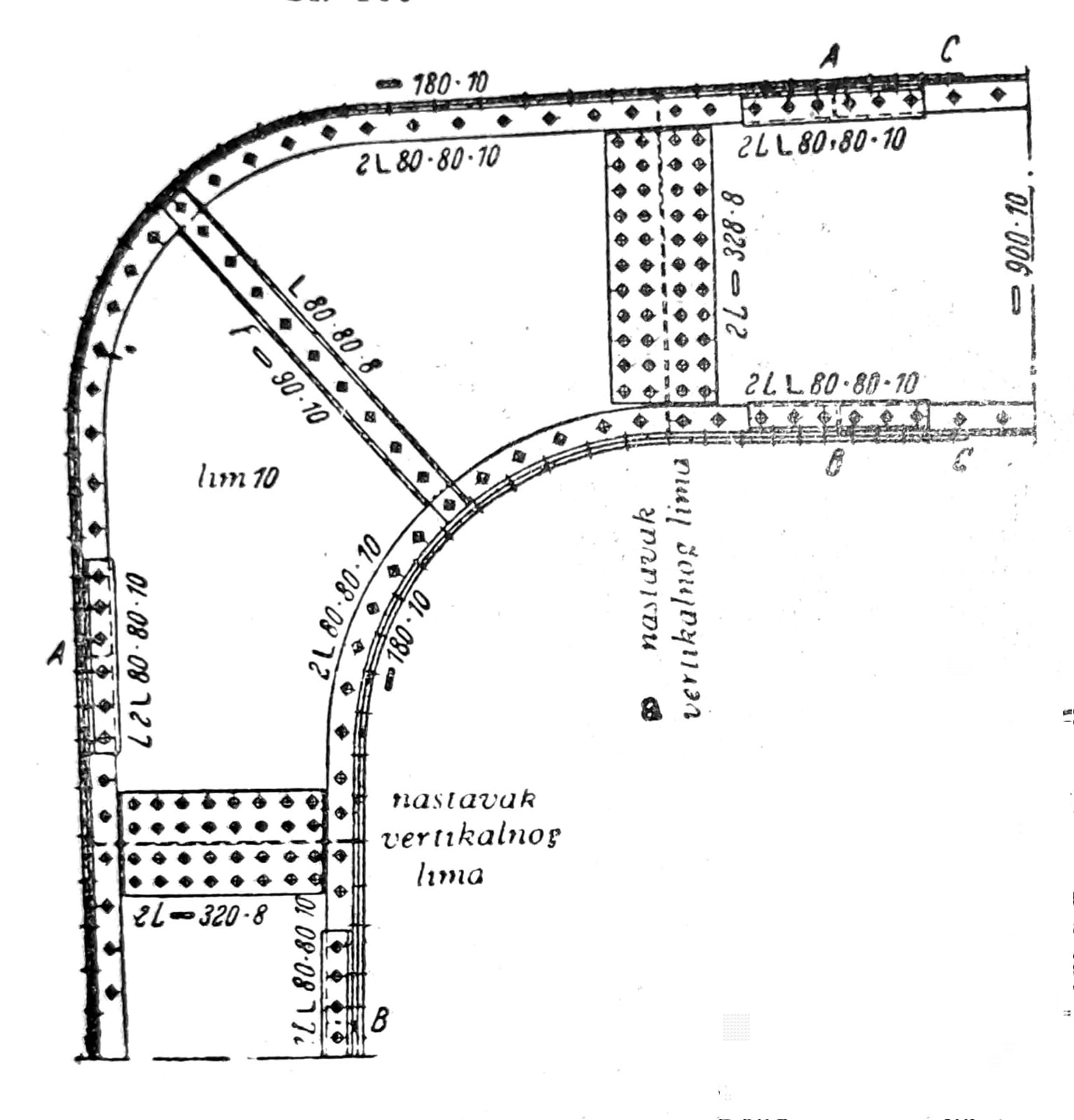
Fig. 17a

Fig. 17b
Inclined joints: In the joints considered so far, the webs stood perpendicular to one another. If, however, the angle is not right, then the angle sections (fig. 18) are rotated; at very acute angles, wedge-shaped shims are used. Use continuity straps and bearing pieces in the given case as in right-angle joints. Bent connecting plates (fig. 19) are connected with large eccentricity and significant additional forces. The execution of inclined joints is facilitated when welded-on connecting plates are used (fig. 20).
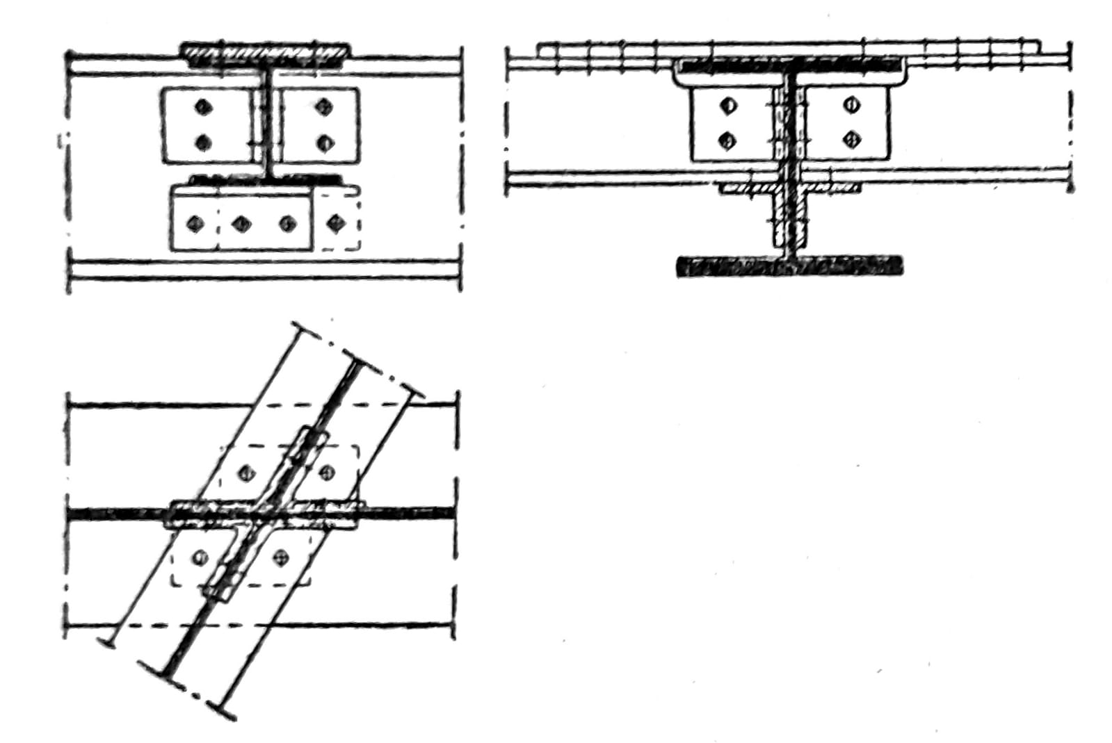
Fig. 18
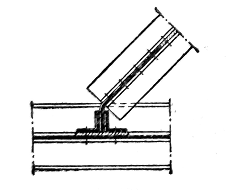
Fig. 19
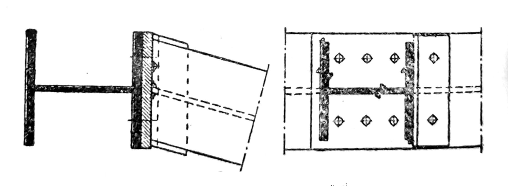
Fig. 20