Important technical and safety notice: This is an archival educational text, not a structural design, static calculation, applicable standard, joint detail or instruction for execution, welding, concreting, shoring, prestressing or rehabilitation. All original formulas, markings, dimensions, materials, procedures and claims are transferred without verification according to today’s regulations. The design and execution of coupled steel-concrete structures belongs exclusively to authorized civil engineers, construction designers, contractors and supervision based on the specific object, load, soil, material and valid standards.
Coupled constructions are not a special service in the current public offer of Savo Kusić. The current focus is wood windows, wood-aluminum windows and custom doors. For a window or door project, you can send a request for quote.
Introduction
In some constructions, reinforced concrete slabs on steel supports are used, such as pavement slabs of bridges on I-longitudinal and transverse girders or ceilings in buildings on I-girders. Previously, such systems were dimensioned under the assumption that these two elements could move with each other and that moments in the direction of the main span were received only by steel supports. The concrete slab transferred the load to the steel girders, but did not participate in receiving the corresponding static values (fig. 1).
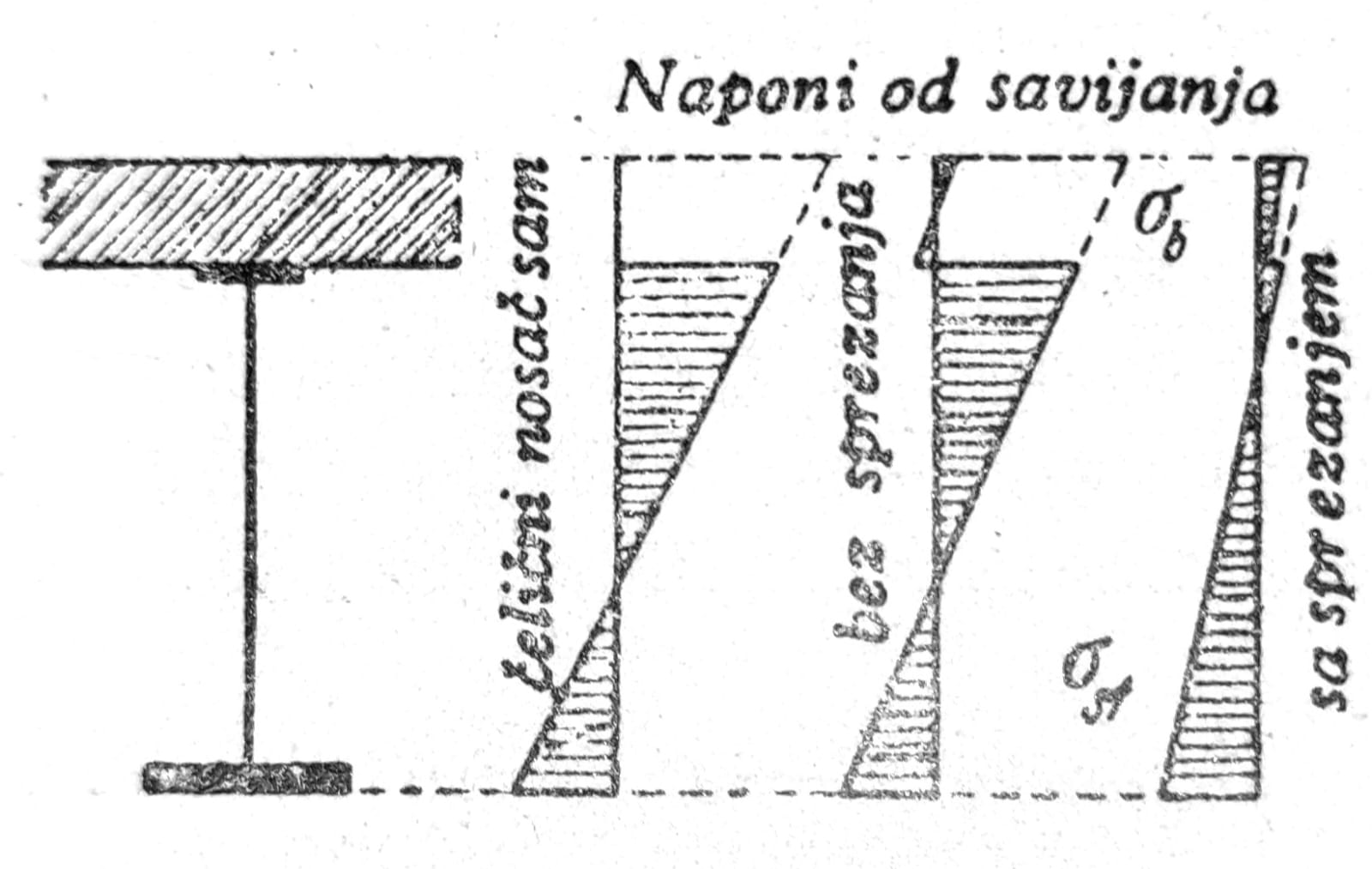
Image 1 — Coupled carrier, system
For this method of construction, transverse joints are foreseen in the concrete slab at regular intervals, in order to enable the shrinkage of the reinforced concrete and avoid undesirable cracks, i.e. supplementary stresses. However, experience has shown that the actual forces in such a system are significantly different from those calculated. At the contact between the reinforced concrete slab and the steel support, a large friction (adhesion stress) occurs, so that both elements always cooperate.
The disadvantage of the unanticipated coupling effect is the appearance of a notch effect on the joints of the concrete slab. Shear stresses along the abutment surface increase sharply near the joint, similar to shear stresses at the ends of side seams. Since the position of the zero line at the joint practically does not change, the normal stresses in the steel support can be significantly higher than those calculated for uniform coupling. Starting from this notch, adhesion mastering can occur which spreads further. Therefore, the joints in the pavement slab do not fulfill their role and are not effective.
Coupled carriers
In the case of coupled supports, it is assumed that the shearing forces on the contact surface between the steel support and the concrete slab can be safely transmitted (forces in the beams). The rule is that the concrete slab rests directly on the upper belt of the steel support and that there are no relative movements. At this so-called rigid coupling uses special means of connection (rods, stirrups, anchors), which are embedded in concrete.
We will consider the case of a coupled beam with a concrete slab without transverse joints. If a certain load (eg bending moment) acts only for a short time, the corresponding stresses and strains Δσ can be calculated, resp. Δε according to elementary strength science, similar to reinforced concrete. Stresses in steel and concrete, at a certain stretching, are in relation to their modulus of elasticity: σst/σb = Est/Eb = n. If the load is long-term, deformations of the concrete due to shrinkage and flow occur. If we mark with ε0 = σ/E0 the deformation due to a short-term load at the moment t = 0,, the deformation increases with a permanent load due to friction until the moment t to the value εt = ε0 (t + φt). Under the same conditions, yield deformations are calculated as if they were proportional to stresses. That is why it is said that Hooke’s law applies to deformations due to flow. The coefficient of flow φt depends on time, class of concrete, external temperature, air humidity, moment of loading of the element, etc.
Instead of bending according to Bernoulli\ and Navier, differential relations appear, i.e. the stress distribution should be determined from the differential equation for flow. As a result of flow, the stresses in the concrete decrease, while the stresses in the steel increase. These stress changes depend, in addition to the cross-section dimensions, on the elastic dimensions and the load moment. Similar consequences as from flow occur from shrinkage of concrete. The amount of shrinkage measures εs depends on the concrete, the method of its production, as well as on the climatic conditions. Concrete shrinkage does not depend on the load applied to the element.
Coupling agents
Coupling means must safely transfer all shearing forces in the concrete and steel surfaces in contact, due to the loads occurring, and thus prevent slipping. In addition, they should receive the oblique main tensioning forces, if due to their size, the concrete section itself cannot receive them. The size of the forces is determined according to the elementary bending theory. The following are considered as means of coupling:
- Coupling anchors: These are round or flat iron plates, welded to the upper belt of the steel girder, which act similarly to bent reinforcement of reinforced concrete beams. They are made as hooks or stirrups, diagonally or vertically. These anchors only act in one direction and are ineffective if the shear force changes sign.
- Girders: They are attached to the upper surface of the steel support, they can receive shear forces in both directions. A distinction should be made between soft and rigid brains in the direction of the shearing force. Soft brain cells suffer significant deformations and unevenly distribute the shearing forces over their surface. Rigid braces provide a better distribution of forces at smaller deformations.

Image 2 — Bridge over the Ruhr River near Herdecke
- Spiral reinforcement: It rests on a steel support and is welded at the points of contact. Spirals are not suitable for significant coupling forces. The same is true for corrugated round steel. As an example of means for coupling on bridges, in fig. 2 the girders of the bridge over the Ruhr near Herdecka are shown (girders 60x40 with vertical stirrups ϕ12, which are welded to the girders themselves, in order to avoid further notches from welding); in fig. 3 means for connecting the transverse girders of one bridge, depending on the size of the transverse force, laterally welded stirrups were used for the girders, as well as directly welded stirrups for the upper belt with special girders. In the case of long stirrups, the stirrups can also be welded on the opposite sides, fig. 4a. In fig. 4b shows a solution with slanted stirrups.
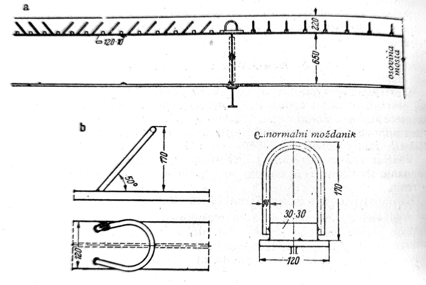
Image 3 — Transverse girder of one bridge
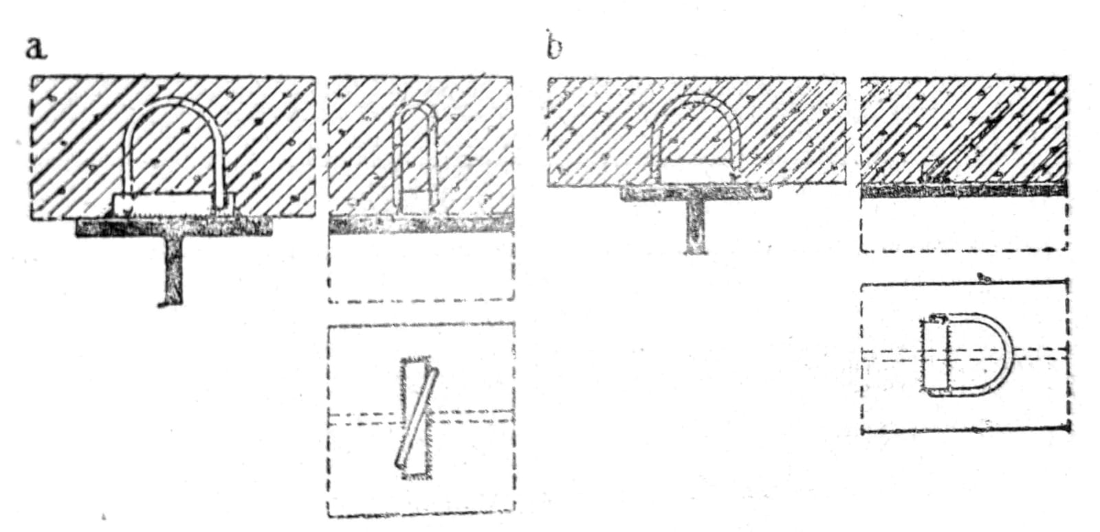
Image 4 — Brains with stirrups
In construction, rigid stirrups with stirrups or just stirrups are also used, but solutions with soft stirrups are also encountered, such as riveted corners. For economic reasons, coupling anchors are more often used, which are butt-welded to a steel support (fig. 5a), or rest on the support with one bent end (fig. 5b). In fig. 5c shows the corresponding solution with displaced hooks. In fig. 6 shows the normal solution of ceiling supports in building construction, namely a) coupled support from I-beams, b) from T-beams, which is created by cutting I-beams. At the ends of the supports, particularly strong end braces should always be provided (fig. 7). Inclined anchors serve to introduce stresses from shrinkage and temperature into the slab.

Image 5 — Coupling Anchors
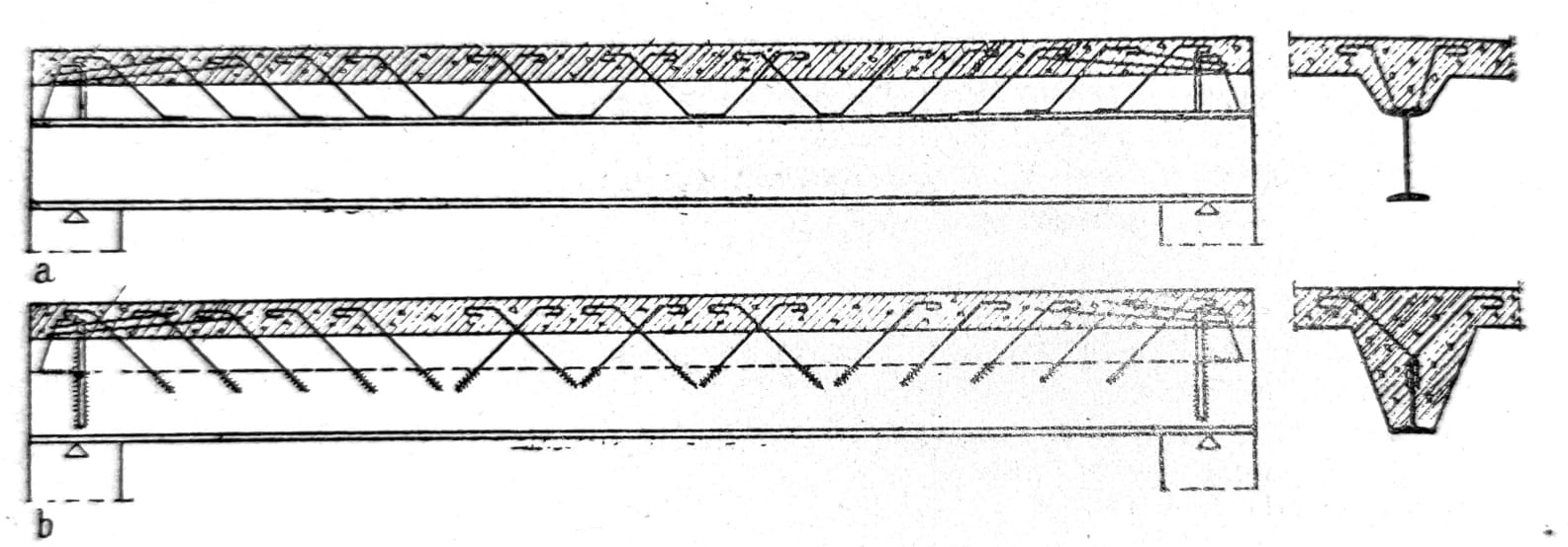
Image 6 — Support of mezzanine structure
Dimensioning of the means for coupling is carried out according to elementary principles. Individual means should receive a shear force corresponding to their spacing. When dimensioning the welded connection of the brain, the overturning moment should be taken into account.
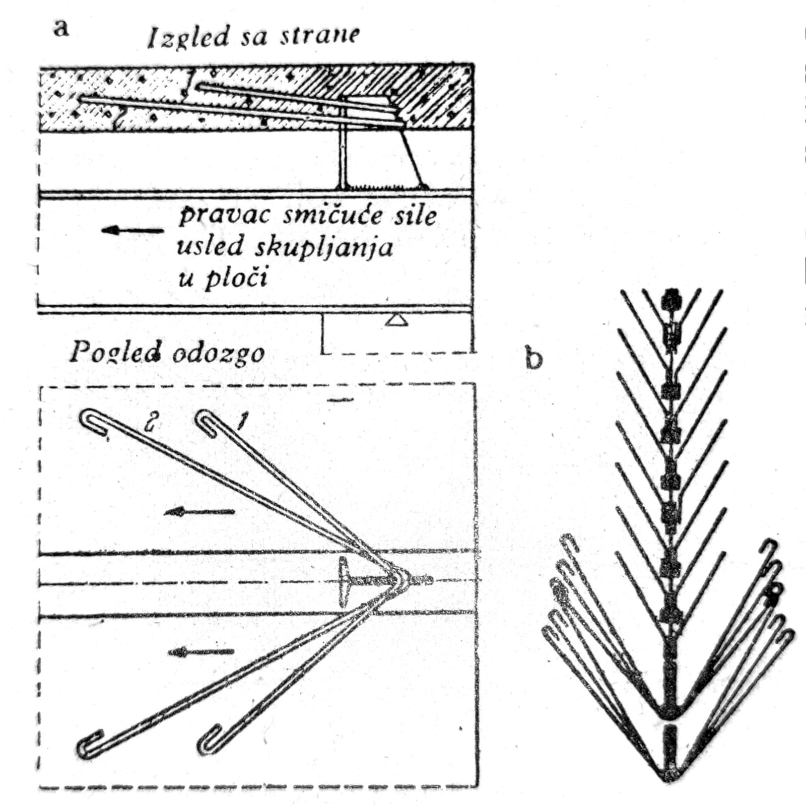
Image 7 — a) End brain with anchoring; b) anchoring
Elastic coupling
Previous presentations have referred to rigid coupling, where the relative displacement between the steel support and the plate is equal to zero, and the coupling means act continuously. The deformation of the coupling means, the local deformation of the concrete and the steel support were neglected.
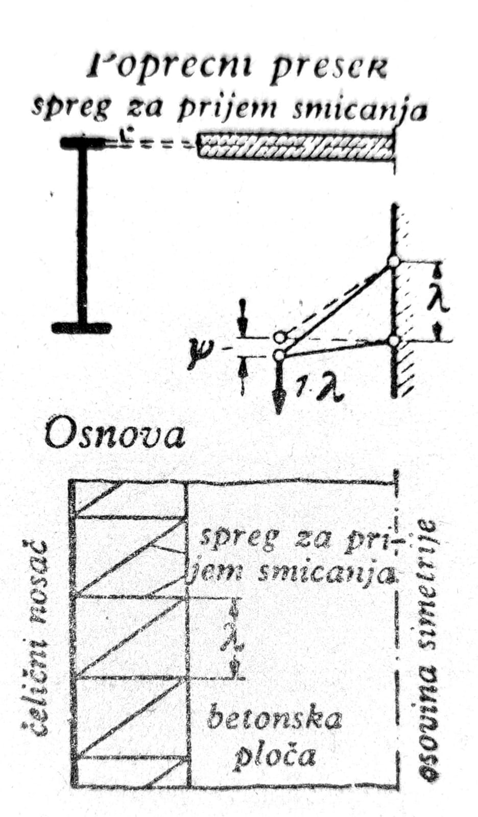
Image 8 — Bracket with elastic coupling
Under the assumption of rigid coupling, the forces transmitted by individual means of coupling are proportional to the transverse force and the spacing of the brain. If significant relative movements between the steel support and the concrete slab occur in certain areas, this causes a noticeable regrouping of forces. Concrete can partially stop acting as a pressure plate of a coupled beam, whereby the maximum values of shear forces are significantly reduced. In fig. 8 is an example of a construction with elastic coupling, similar to the bridge over the Rhine, Koln-Rodenkirchen. In fig. 9 shows the effect of elastic coupling on a continuous support, for a concentrated force and a fully evenly distributed load. The displacement ψ, which is a measure of the stiffness of the coupling for receiving shear, is defined in fig. 8. The influence of the elastic coupling is therefore very large, if the properties of the coupling are chosen purposefully to receive shear.

Figure 9 — Example for a bridge with elastic coupling
Calculation of coupled structures
In principle, it is economical that the thickness of the concrete slab should be as small as possible, while the minimum thicknesses determined by the regulations should be adhered to.
Statically determined structures
In the case of statically determined constructions (eg simple beams), the static influences in the common section for a certain load are constant, or independent of time. Only the bending moments and normal forces in certain parts of the section are variable due to the effects of flow and shrinkage.
The effect of shrinkage can be represented as a corresponding temperature difference between the steel girder and the concrete slab. As a result of concrete shrinkage, internal stresses appear in the coupled section, namely tensile stresses from shrinkage in the concrete, whose shrinkage is prevented by the influence of the steel support (as well as the reinforcement itself), while corresponding compressive stresses occur in the steel section (fig. 10). Shrinkage increases with time to a final value according to a single exponential function. Since shrinkage stresses also increase with shrinkage deformations, this results in so-called shrinkage flow.

Figure 10 — a) Contraction of a free plate without coupling; b) stresses due to shrinkage in coupled supports
Depending on the static system that assumes the self-weight of the concrete slab, it differs: coupling only for the moving load (only the steel support takes its own weight, and the coupled system receives only the loads that act on the finished structure), coupling for the own weight and moving load (the entire self-weight and the moving load act on the coupled system).
The first case occurs when the steel girders serve as formwork supports, without being supported, and during concreting, they can bend in the field (fig. 11a). In this case, the steel support itself takes the weight of the concrete and formwork. Bonding occurs only when the concrete is hard enough (fig. 11b), so the support must not be loaded immediately after concreting, in order to avoid damage or too much flow of the concrete.
In the second case, when the self-weight of the concrete slab is also received by the coupled system (fig. 11c), it is assumed that the steel support is supported during concreting in sufficient places, so that it does not receive significant bending moments. The stress distribution after removing the scaffolding is shown in fig. 11d.

Figure 11 — Coupling for moving and self-loading, with stress distributions before and after removing the scaffolding
Prestressing
In the case of simple beams, smaller tensile stresses occur in the concrete only due to shrinkage and temperature differences. Substantial tensile stresses occur in overhang beams, continuous girders and other structures, and these can cause cracks in the concrete. If cracks appear in the area of negative moments, the coupling effect is lost. Therefore, it is useful to induce small compressive stresses in the concrete slab in advance in order to safely avoid the formation of cracks due to concrete shrinkage. Tensile stresses in the concrete slab of coupled beams can be reduced:
1. By corresponding negative preloading of the steel girder (pretensioning of the upper edge). At the same time, the sequence of concreting should be carefully studied.
2. By raising and lowering the middle supports of continuous supports. whereby, with the appropriate procedure, compressive stresses can be induced in the concrete slab of the coupled support.
3. By prestressing. The simplest case is when a free concrete slab is prestressed, and only subsequently connected to a steel support. The advantage of this procedure is a relatively small prestressing force, since the compressed belt of the steel support is not prestressed. This girder receives bending moments only due to the flow and shrinkage of the concrete slab, so it remains straight due to the prestressing force. In fig. 12a shows the stress distribution for this case of prestressing (t=0), and in fig. 12b final state at the end of flow (t=tE) and in fig. 12c bending stresses due to short-term moment loading (t=a). In fig. 12d shows the stress distribution for t=0 in the case of prestressing of the bonded concrete slab.

Figure 12 — Prestressing of free-standing concrete slab with subsequent coupling
Statically indeterminate structures
Continuous girders and similar structures receive negative bending moments, which often cause high tensile stresses in the reinforced concrete slab. Cracks are undesirable, especially in bridges, considering the service life of the coupled girders and the effect of notches on the cracks. Statically indeterminate systems are calculated for short-term loads (moving loads) according to the usual methods of statics for an unchanged system. The corresponding static quantities and deformations are the same as in an ideally elastic system. Under the effect of constant loading, especially high prestressing, large flow always occurs. When determining the prestressing force, the friction of the bent prestressing elements should be taken into account. During construction, the overhang of coupled bridges should be carefully selected. Ready-made coupled supports are very rigid, so it is almost impossible to make subsequent corrections of the height position. The final level is achieved only after several years, considering the flow. That leveling is uncertain to some extent, since the effects of shrinkage and liquefaction are variable, depending on climatic conditions that cannot be predicted.
Conclusion
The application of coupling is not limited to sheet metal beams, but can also include supports for stiffening Langer beams, suspension bridges, etc. as well as lattice girders with a carriageway up or down. Lattice bridges - high tensile stresses occur in the road slabs near the roadway below, since these slabs have to follow to a greater or lesser extent the elongation of the tensioned belt of the main girder. Adequate longitudinal prestressing is required to avoid cracks. In fig. 13 is a borderline case where the steel grid no longer has a lower belt, and its role is completely taken over by a reinforced concrete slab prestressed in both directions. In fig. 13b you can see the 60x180 mm section channels in the support itself.
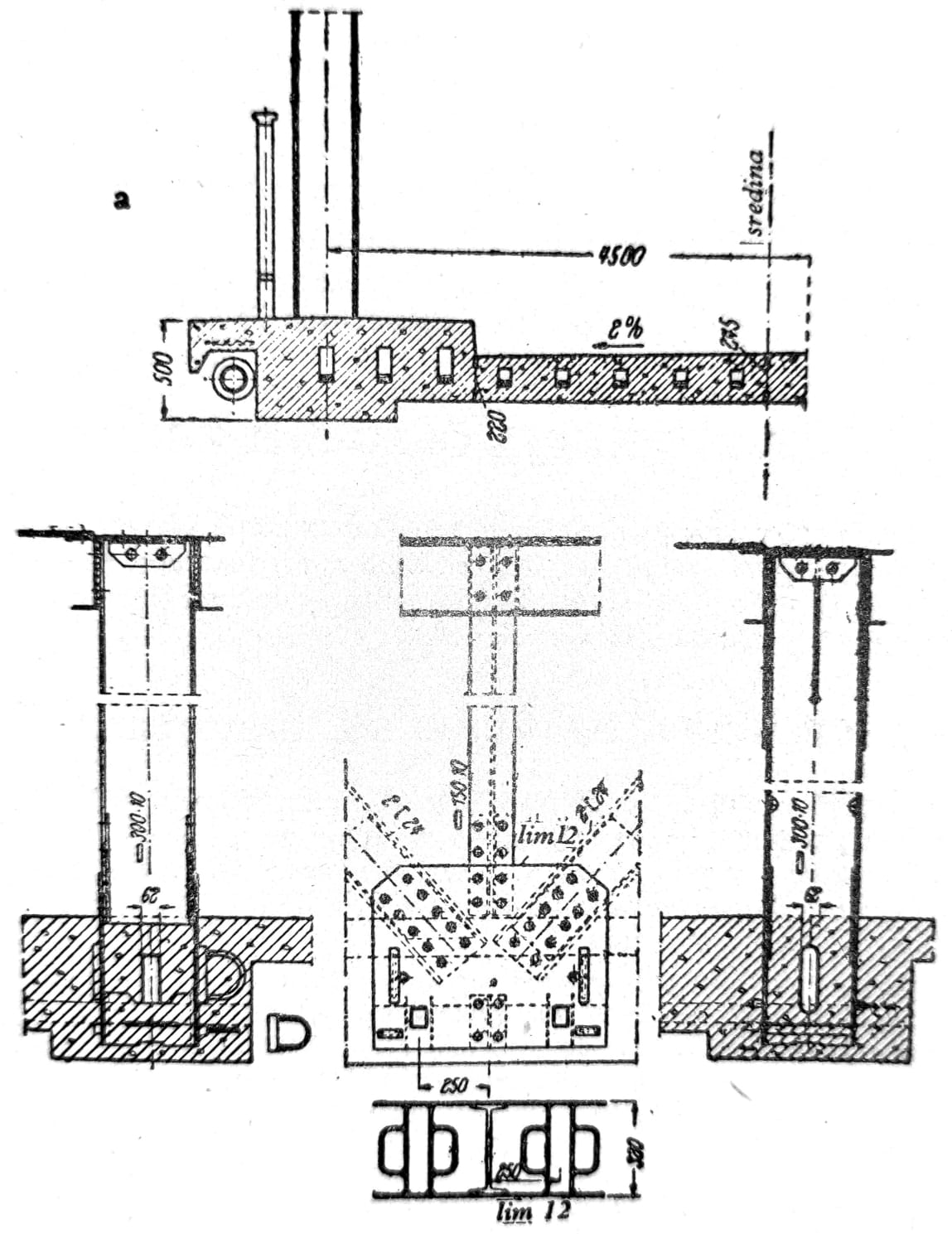
Image 13 — Gahle Bridge: a) section; b) junction of the lower belt, left at the main station, right at Vešaljka