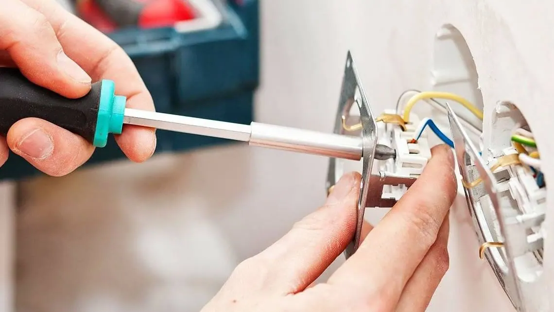
Safety note: This is an archival educational text from 2017, not instructions for carrying out electrical installation work yourself. Electrical installations and repairs should be entrusted to a qualified electrician, in accordance with current regulations and the condition of the particular installation.
Why electricity requires particular caution
When we travel by plane, we are very excited; when we cross a street, we are very careful; and in deep water we swim more correctly. Yet we are often careless when working with electricity, which is much more dangerous than any of these. This carelessness probably comes from the fact that electricity has become our everyday companion and we can hardly imagine life without it.
Electric current is, however, dangerous to life, and we must be especially careful when working around it. Even so-called low-voltage networks (110–220–380 V) are dangerous to life, let alone power-line voltages of several tens of thousands of volts. Voltages of 42 V are used in particularly dangerous places, but even this voltage can cause an electric shock, while voltages above 50 V will certainly cause one. Electric shocks from battery-powered devices using so-called extra-low voltages are less dangerous, but caution is still required because some such devices — for example, a lamp used to illuminate a tent — may contain a transformed high voltage that is dangerous to life.
Voltage, current and power
The preceding passage might suggest that the danger electricity poses to life depends only on voltage. However, current, expressed in amperes (symbol A), also has a considerable influence. Multiplying these two quantities gives electrical power, expressed in watts (symbol W). Voltage, expressed in volts (symbol V), is marked on every light bulb and electrical appliance. The current marking, ampere (A), is seen less often. It is usually marked on fuses and means that when its value is exceeded, the fuse wire melts and automatically interrupts the electricity supply. The power marking in watts appears more frequently: it is found on electrical appliances and indicates how much power the device “takes”, that is, how many watts it has.
If two of these three values are known, the third can easily be calculated using the simple formula V × A = W, from which A = W / V or V = W / A.
Voltage, expressed in volts (V), can be compared with pressure in a water-supply network, while current, expressed in amperes (A), can be compared with the amount of water flowing from the network in one second. That amount depends on the network pressure and the flow capacity of the tap. The flow capacity is determined by the part of the network and its connections that has the smallest capacity and greatest resistance. Power, expressed in watts, can be compared with the energy of water leaving the tap and its ability to perform work, for example to turn a water wheel (Figure 1).

Comparison of voltage, current and power with water pressure, flow and output.
One example: a 220 V cooker plate with an output of one kilowatt (1,000 watts) operates at a current of 1,000 / 220 = 4.5 amperes.
If the network is protected by a 6-ampere fuse, switching on another 500-watt load, such as an electric iron, will cause the fuse to melt and leave us without electricity.
Cartridge fuses and overload protection
Since fuses have been mentioned, this is an opportunity to examine them in more detail. Fuses protect household appliances and the other network installations in a home, as well as conductors in walls, from overload and the consequences of short circuits, and provide protection against touch voltage.
An overload can occur if an existing household network is loaded with new electrical appliances and they are used at the same time. It can also occur if, for example, laundry becomes jammed in a washing machine whose load the network normally supports, causing its motor to stop. In such cases the motor “draws” several times its rated current from the network. Overloading also frequently occurs when all cooker rings and even the electric oven are used at the same time, which the existing network may likewise be unable to support. A “short circuit” is entirely different in nature and usually occurs when a metallic connection forms between conductors at different voltages, in most cases because of insulation failure — for example, if a hot iron accidentally touches the insulation of its supply lead.
The operating principle of a cartridge fuse is as follows: a conductor whose cross-section permits only the allowed current to pass and which melts under the concentrated heat of a stronger current is included in the circuit to be protected. Fuses are used so that this protective conductor can be replaced easily and safely and connected easily to the network. A fuse consists of four parts: the base, the gauge ring, the threaded cap and the fuse link (Figure 2).

Parts of a cartridge fuse.
The base and threaded cap require no explanation. The gauge ring is made of porcelain or an artificial material and, once installed, rests against the lower part of the base. The opening in the centre of the gauge ring ensures that the circuit is closed only by a fuse link that passes through this opening. The upper surface of the gauge ring is coloured, and this colour should be identical to that of the disc on the fuse link. A link of another colour may also be used provided that the cavity in the gauge ring does not prevent its insertion — that is, if the link melts at a lower current. The colours and their corresponding currents are given in the table.
Fuse links can be fast or time-delay types: under the same overload, the first melts quickly and the second more slowly. Melting time depends on the size of the overload, but in a short circuit both types of cartridge fuse will burn out in a fraction of a second.
The fusible wire in the link is placed in quartz sand so that it will not break because of vibration. It is important to know that electricity in a home is switched off most safely by carefully unscrewing the fuse. The type designation for cartridge fuses used for domestic electricity is DZ II (Diazed, with a standard connecting thread).
Characteristic colours of DZ II fuse links
| Rated current, A | Colour |
|---|---|
| 2 | pink |
| 4 | brown |
| 6 | green |
| 10 | red |
| 15 | grey |
| 20 | blue |
| 25 | yellow |
Protection classes, protective conductors and sockets
Besides fuses, other solutions and devices protect people who work with electricity. One such solution is the double insulation used on better-quality household power tools. Machines protected in this way do not need to be earthed and have no separate terminals for protective conductors; it is enough simply to place the plug in the socket. The double-insulation symbol belonging to protection class II is a larger square containing a smaller square. Class O devices have no protection, class I devices must be protectively earthed, and class III consists of devices operating at low voltage.
In a protective-conductor system, there is a separate third conductor in the network that is connected through a protective plug to the third conductor in the appliance. If a short circuit occurs in the appliance, current will also flow through this third protective conductor. When it reaches the electricity meter, it trips the automatic device or switches off the small circuit breaker. This is a small automatic device used instead of a meter breaker with a closing latch; in the event of a short circuit, it switches off the electricity supply within 5 seconds. Once the fault has been removed, it can be switched on again by pressing the larger, dark-coloured, square button.
It is very important that appliances with touch protection be connected to a network that also has a third protective conductor. A special shape of protective plug prevents connection to an unsuitable socket. Touch-protected plugs and sockets are easily recognised by the built-in metal rails parallel to the pins (Figure 3).

Protection symbols and different types of plugs and sockets.
A common and life-threatening mistake is to extend the cable of an appliance so that one end is touch-protected while the other end, containing the mains plug, is not. Such an extension lead can be connected to a touch-protected network or to a network without such protection. The cable of a touch-protected appliance can be connected at the other end, giving the user the impression that touch protection is present when it is not. An extension lead should therefore be touch-protected at both ends or unprotected at both ends. One more point about extension leads: it is advisable to fasten their parts together during use in a way that still allows them to be separated later, for example with a rubber strap. They should not be placed on the ground, but on a table or chair or hung from a door so that they do not come into contact with water.
Colours of conductor insulation
Knowing conductor colours is important because the colour designations have changed and both new and old markings may be encountered. In both the new and old markings for single-phase and three-phase electricity, the phase conductor is black. The conductor used for neutralisation used to be grey and is now blue. The third conductor for touch protection used to be red and is now green-yellow with longitudinal stripes.
Planning installations and laying cables
Installing an electrical system is not a job for an unqualified all-rounder, especially when the network is at low voltage rather than extra-low voltage. Electrical installation work is best entrusted only to qualified tradespeople, even when a job of only a few minutes requires a considerable expense. This applies to installations in new buildings and flats as well, although work may be undertaken more confidently while the electricity has not yet been connected. Even here, only “mechanical” work should be accepted, with the following points in mind:
- For every m² of the area to be illuminated, approximately 10 watts should be allowed.
- It is advisable to plan lighting with glare protection. Although this gives less illumination because of scattering and refraction, the protected light also protects our eyes.
- A separate light should be planned above or beside permanent work positions and working areas, such as a kitchen table, cooker, writing desk or bathroom mirror.
- Light switches should be placed in accessible locations while also satisfying aesthetic requirements, or should be at least 1.2 m away from plumbing and other installations. Light switches should be avoided in rooms containing humid air and steam, such as laundries and bathrooms.
- Switches and plugs should comply with technical safety regulations. Switches should be double-pole, and plugs should be inaccessible to children or “protected”.
- At worktables, make sure that light comes from the left. Enough sockets should be installed to allow household appliances and portable light sources to be used without extension leads. Arcs drawn from socket positions with a radius equal to cable length should cover the entire room.
- An electric bell should operate through a low-voltage reducer, completely separated from the low-voltage conductor.
- Cables may be laid only by an authorised electrician who follows technical and safety regulations to the greatest extent.
- A good builder of a family house leaves room during construction for larger chases, openings and similar spaces where cables and other electrical installations will be placed, thereby reducing the amount of chiselling required (Figure 4).

Example positions of cables and installations in a wall.
A similar approach should be taken when plastering. At the positions where cables will be laid, battens with a diamond-shaped cross-section 1.5–3.0 cm wide should be placed with their wider side facing outward. Before installation work begins, these battens are removed and protective conduits and conductors are placed in their positions without chiselling the plaster.
If we assist with chiselling, protective glasses and possibly a finger guard must be used. It is advisable to work with a larger number of smaller blows. Care must be taken not to chisel new walls unnecessarily; the position and size of the required chase should be marked precisely in advance.
In dry buildings, it is best to use paper protective conduits. They are somewhat more expensive, but conductors can be changed and repaired easily inside them. Short but sound used conduits can be cleaned and reused for shorter sections. More recently, conductors with double PVC insulation have been laid directly beneath the plaster. This solution is cheaper but less practical because the plaster must be removed to locate a possible fault. If possible, previously used conductors should not be used because hidden internal breaks are very difficult to identify. Used insulating material or sheathing is usually not standard or has become fatigued, so its use can be dangerous to life — the wall may “give shocks” — particularly in damp rooms.
The greatest attention should be paid to positioning and installing household appliances. We must personally ask and verify whether an appliance has an earth connection and, if it does, where it should be connected, and what safety measures are prescribed for it, for example fitting a pressure-reducing valve to a water heater. Cooking and heating appliances, refrigerators and similar devices should be placed in easily accessible positions and at a suitable height, with their surroundings protected from fire.
The types and methods of protection against accidental contact for household appliances and loads, depending on the installation environment, are set out in the applicable technical regulations for electrical power installations in buildings, including double insulation and protective conductors.
Archival description of a household service connection
The building owner can also help with the household connection by assisting with its fastening over roof supports or support insulators embedded in a wall. It should be known that a distance of no more than 25 m can be spanned without a pole. If the distance is greater, one or more poles must be installed. An overhead conductor should be at least 3 m high, or at least 5 m where vehicles pass below it (Figure 5).

Overhead conductor height and span.
The height of a household connection above a roof support should be at least 100 cm, or 200 cm if the roof is flat. The pipe must be tied to the roof support at no fewer than two points with steel cable, and it is useful if the pipe is galvanised.
At the joint between the pipe and the roof support, the finishing sheet metal should be attached to the pipe with solder and putty so that its upper side is beneath the roof tile and its lower side above the tile. This prevents the roof from leaking. A household connection may also be installed on a side wall of the building. In this case, the fastening clamps should be spaced at least 100 cm apart. A lead or PVC pipe is placed in an arc between the lower part of the pipe and the entry bend, and the lower part of the pipe is drilled to drain any water that may have entered it. If the building is more than 5 m high, the household connection can also be made through the necessary insulators embedded in the wall. The distance between the insulators and the gutter must be at least 50 cm. The entry bend should be placed on the right-hand side of the insulator (Figure 6). In flats, it is best to place conductors in Bergmann conduits (Figure 7).

Household connection over a roof support and on a side wall.

Examples of routing an installation through Bergmann conduits.
Archival description of joining and insulating conductors
Electrical conductors should be connected so that the circuit is completed without fault. When insulated conductors are joined, particular care should be taken to ensure that the insulation is sound.
It is best to solder the ends of conductors. For such a connection, remove 20–25 mm of insulation from both conductors and clean the conductor ends with abrasive paper or scrape them with a knife. Bring the cleaned ends together, twist them several times and then solder them. After soldering, the joint must be insulated thoroughly.
Wrapping with insulating tape begins on the insulated part of the conductor, continues across the soldered part and finishes again on the insulated part. It is best to place two layers of insulation over the joint (Figure 8).

Illustrated steps for joining and insulating conductors.
Conductor ends can also be joined without breaking them. In this case, clean 30–35 mm at the ends of both conductors, bend the cleaned sections at the middle and wrap them firmly around one another. Finally, insulate them carefully. With careful work, plugs and switches may also be fitted on appliances whose connections can be isolated from the network. The assembly and appearance of the most commonly used plugs are shown in the illustrations.
The video below also shows one excellent method of joining wires.
A simple plug is made as a sleeve with pins: 1. conductor, 2. cores, 3. banana pins, 4. clamping screws. It is important to strip the cores only for the required length without cutting into or breaking the metal conductor; to make sure that the screws clamp the cores firmly; that the sleeves are also firm in their seats; and finally that the screw joining the two halves tightens the plug without looseness (Figures 9 and 10).

Assembling a simple plug.

Parts and connection points of a plug.
The cleaned conductor ends in plugs that can withstand higher loads should be lightly tinned so that they are firmer during assembly. The end of the conductor should be bent into a loop in the same direction as the screw tightens so that the loop does not open during tightening. Loose plug contacts can be widened using a screwdriver placed in the slot and pliers: 1. conductor, 2. contacts, 3. tinning, 4. bending the end, 5. loop (Figure 11).

Preparing plug conductors and contacts.
On a plug with protection against accidental contact, the phase cores should be fastened first and the green-yellow core fastened in the centre afterward (Figure 10). On cables with worn textile insulation, it is advisable to tie the sheath (upper part of Figure 12).

Plug connections and a schematic view of a fluorescent lamp.
Fluorescent lamps
One common electrical installation task is fitting fluorescent lamps, although they are no longer as highly valued because of their known disadvantages. Their advantage, besides low electricity consumption, is that they can be installed in a home with little effort. In addition to the lamp, an internally hollow mounting board, a pair of lamp holders with a starter, a ballast and a capacitor are required.
First, make a mounting board from plywood or a thin soft board that is 5–6 cm longer than the lamp. Make a 6–7 cm cavity inside the board to contain the ballast and capacitor. Then fasten one lamp holder to the board with screws, insert the lamp and fasten the second holder. Place the starter beside one holder and place the ballast and capacitor in the cavity (lower part of Figure 12).
The lamp can now be wired. First extend one red-coloured conductor from the ballast and connect it to one lamp terminal. Connect a short conductor to the other holder terminal and connect its other end to one starter-holder terminal. This is necessary only if the starter and holder are not already connected. Then connect a longer conductor to the other starter-holder terminal and its free end to the second lamp holder. Connect another conductor to the other terminal of that holder and connect its other end to the second free red end of the ballast. Finally, connect the network conductors to the white-coloured ends of the ballast, first using a brief contact to test whether the lamp works. All that remains is to connect the capacitor leads to the white-coloured ends of the ballast. It is important to know that fluorescent lamps can be supplied only from an alternating-current network and should be switched on and off as little as possible.
The most important rules from the source text
- Work only on an appliance that is not live, meaning that its plug has been removed. Wait for the appliance to cool and for capacitors to discharge. If working on a part permanently connected to the network, such as a switch, turn off the electricity meter and remove the fuses. Neither measure by itself provides one hundred per cent safety.
- A fuse must never be connected or “bridged” with thicker wire.
- Work only with sound electrical installation tools whose insulated handles are undamaged.
- Do not work with wet hands; always keep a dry cloth nearby for drying them.
- Always use an extension cable that is protected against accidental contact at both ends.
- When purchasing electrical appliances, give preference to those supplied with proper instructions.
- Never touch a water pipe, central-heating pipe or radiator while holding any electrical appliance.
- Be particularly careful when working with electrical appliances in rooms with humid air. In a bathroom or bath, do not touch an electrical switch, conductor or similar part. Fill or empty a spin dryer or washing machine only while it is switched off. Use a rubber mat on the floor when washing and ironing. Fill or empty an electric cooking appliance or coffee maker only after removing its plug from the socket.
- Use only conductors with suitable cross-sections. Do not remove plugs from sockets by pulling the cable. Strip insulation only for the absolutely necessary length, insulate only with sound insulating tape, and bind and secure the wrapped tape with thread.
- Keep a torch, test lamp, fuses and a phase-testing “pencil” beside the electricity meter.
- At the slightest doubt or uncertainty, switch off the appliance, stop the repair and entrust further work to a specialist.
- Before connecting a repaired appliance to the network, check it with a low-voltage test lamp powered by a battery.
- In the event of electric shock, first switch off the electricity by removing the plug or fuse and then assist the injured person.
Related topics: articles about household installations, basic tools, window and door production and contact.