Fundamentals of static calculation
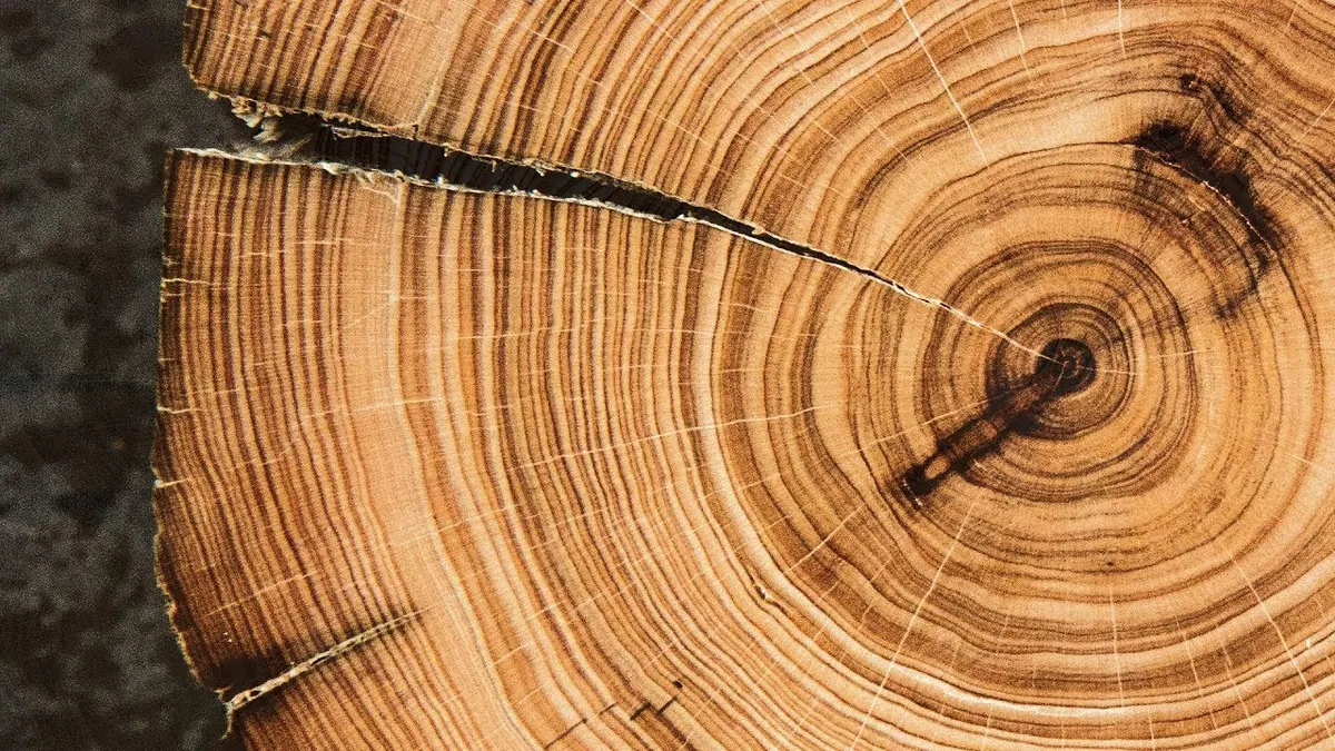
Wood is a natural material and, because of its anatomical structure, a non-homogeneous construction material. It can be compared to a bundle of tubes arranged individually in parallel and in rings around the pith of the trunk — annual rings or growth rings — which have different cross-sections and wall thicknesses throughout, namely earlywood and latewood.
The strengths of wood depend on the conditions under which the tree grew, and they are also influenced to a large extent by wood defects, developmental irregularities, the age of the tree at the time of felling and use, and especially its moisture content.
The average strength value not only differs between individual trees from the same area, but also decreases within the same tree from the thicker towards the thinner end. In a cross-section, the youngest annual rings beneath the bark represent the best and hardest wood. A forestry specialist can influence the properties of wood only to a limited extent, while the user is scarcely able to alter its strength properties by simple means.
Compressive strength
Compression parallel to the grain
When test specimens, which mostly have a square cross-section, are examined, failure occurs because the walls of the fibre cells buckle into the cavities, without any clearly expressed transverse expansion being identifiable beforehand. This buckling begins at places with minor structural irregularities, which in most cases cannot even be noticed externally, or starts at the upper or lower compressed surface.
The permissible compressive stress for softwood — whether spruce, pine or fir — is set at 8.5 MPa, and at 9 MPa for larch. For hardwood, oak or beech, it is 10 MPa.
Generally speaking, the actual average compressive strength, at least for oak, is no greater than that of softwood. Nevertheless, this value is justified because hardwood is in practice used in structures only in small pieces, so wood with large knots or irregular development can be avoided. Oak is overestimated. Young oak, up to 30 years old, appears to be considerably tougher and stronger than the wood of older trees.
Quality class I permits a strength of up to 11 MPa for softwood, 11.5 MPa for larch and 12 MPa for oak and beech. Quality class III establishes values of 6 MPa for softwood and 7 MPa for oak and beech.
Compression perpendicular to the grain
Perpendicular to the grain, the failure phenomena differ from those caused by compression parallel to the grain. Strength under transverse compression depends mainly on the strength shown by the uncompacted amount of earlywood in the annual ring. Latewood, on which the value of axial compressive strength depends, has the role of distributing the load under transverse compression.
During testing, the indicator showing the magnitude of the force constantly retains its highest attained position. In the case of a fully loaded cross-section, compressive strength perpendicular to the grain for softwood amounts to between 1/7 and 1/10 of the strength parallel to the grain, and for hardwood between 1/3 and 1/5 of the strength parallel to the grain.
Tensile strength
Tensile strength has been examined to a considerably lesser extent than compressive strength. This may partly be because producing and testing suitable specimens takes a great deal of time and is expensive.
Irregularity in the structure of wood is particularly evident in tensile strength. As with compressive strength, in addition to the width of the growth rings, the proportion of latewood is of decisive importance. Earlywood fails before latewood, so the strengths of earlywood and latewood cannot be added together. The influence of knots and developmental irregularities is more pronounced than in compressive strength. Any curve or wave caused by the proximity of knots, which need not even be located on the member itself, is enough to reduce failure strength to as little as one quarter of the tensile strength of defect-free wood.
The weakest points of tension members are the structural joints, where the reductions caused by notches for dowels are also greatest. Here, especially in the side members or straps, bending stresses occur that are not covered by the calculation.
The permissible stresses for quality class I softwood are 10.5 MPa, and 11 MPa for oak and beech. The use of quality class III timber is excluded for tension members.

Apparatus for testing the tensile strength of wood.
Bending strength
The assumptions on which Navier’s formula for bending calculations is based also apply to wood with good approximation, but only at low loads. At higher loads, displacements occur such that the actual edge stress due to compression is lower than the calculated value, while the opposite applies to tensile stress. The actual neutral axis shifts towards the tension side.

Figures 1 and 2 — Member failure and stress distribution during bending.
The calculated bending strength at failure is between 1.4 and 2 times greater than the compressive strength and, with minor exceptions, lower than the tensile strength. If knots and irregularities occur near the maximum moments and maximum edge stresses, reductions of up to 50% occur.
It should be emphasised that bending strength under a long-term static load is approximately half the bending strength determined in the usual manner. If the load is frequently repeated in whole or in part, the load-bearing capacity will continue to decrease depending on the extent to which the moving load contributes to the total load.
The permissible bending stress for quality class III softwood is 7 MPa, while values of 10 MPa and 13 MPa are established for quality classes II and I respectively. For continuous beams without hinges from the latter two classes, stresses of 11 MPa and 14 MPa are specified because such beams provide greater safety.
When sizing beams exposed to bending, in many cases the bending stress is not decisive; the permissible deflection is. For floor-structure beams, deflection due to permanent or imposed load must not exceed 1/300 of the span. For a simply supported beam under a uniformly distributed load, the ratio between span and height may be no greater than 16 at a permissible bending stress of 10 MPa.
For short, heavily loaded beams and complex cross-sections, shear stress is decisive. The modulus of elasticity is important for deflection, as it is for buckling strength and the calculation of statically indeterminate structures. The magnitude of the modulus of elasticity varies widely depending on timber quality. The modulus of elasticity of softwood is 10,000 MPa; perpendicular to the grain, this value is 300 MPa for softwood timber and 600 MPa for oak and beech timber.

Apparatus for testing the bending strength of wood.
Shear strength
Wood has low strength in shear. Shear-strength values can vary considerably because of cracks in the wood.
An upper limit of 0.9 MPa has been established for softwood timber of all three quality classes. For quality classes II and III oak and beech timber, the maximum value is 1 MPa, and 1.2 MPa for class I.
If these stresses produce end projections that are too short, it is recommended that the stresses not be fully utilised. When the end projections are short, there is a considerable risk that shrinkage cracks will form in the shear plane, which may lead to a complete loss of load-bearing capacity.

Apparatus for testing the shear strength of wood.
Buckling strength
If members are exposed to compression, buckling must be checked by calculation. The correct selection of buckling length is particularly important. Members must be secured by bracing against lateral deflection. If this cannot be achieved sufficiently, a greater buckling length should be used in the calculation.

Figures 3 and 4 — Solid and built-up cross-sections with material and non-material axes.
For built-up compression members, the calculation in relation to the material axis, the x-axis in Figures 4a and 4b, is carried out in the same way as for solid cross-sections, with the width of the entire member taken as the sum of the widths d of the individual elements.
For buckling in relation to the non-material axis, the y-axis in Figures 4a, 4b and 4c and the x-axis in Figure 4c, perfect composite action of the individual cross-sections cannot be assumed because the transverse connections of timber members are flexible. The following relationships apply to the two-part cross-section shown in Figure 4a:

Original formulae for calculating a two-part cross-section.
Built-up compression members are mainly used only where connections require them, that is, when solid-section elements in the required dimensions cannot be obtained. To approximate solid cross-sections as closely as possible, continuous longitudinal connections are always recommended.
Related topics: load-bearing timber structures, floor structures, wood defects, wood moisture content and timber.