PHENOMENA UNDER STATIC LOADING
Deformation of a material under the influence of stress is a very complex phenomenon, so it must be simplified in various ways in order to be understood. One of these simplifications is the assumption that loads are applied gradually, as is done, for example, with specimens during tension and compression tests.
If a steel bar loaded in tension is subjected to a gradually increasing load and its elongation ℇ is measured, the diagram shown in the figure is obtained.
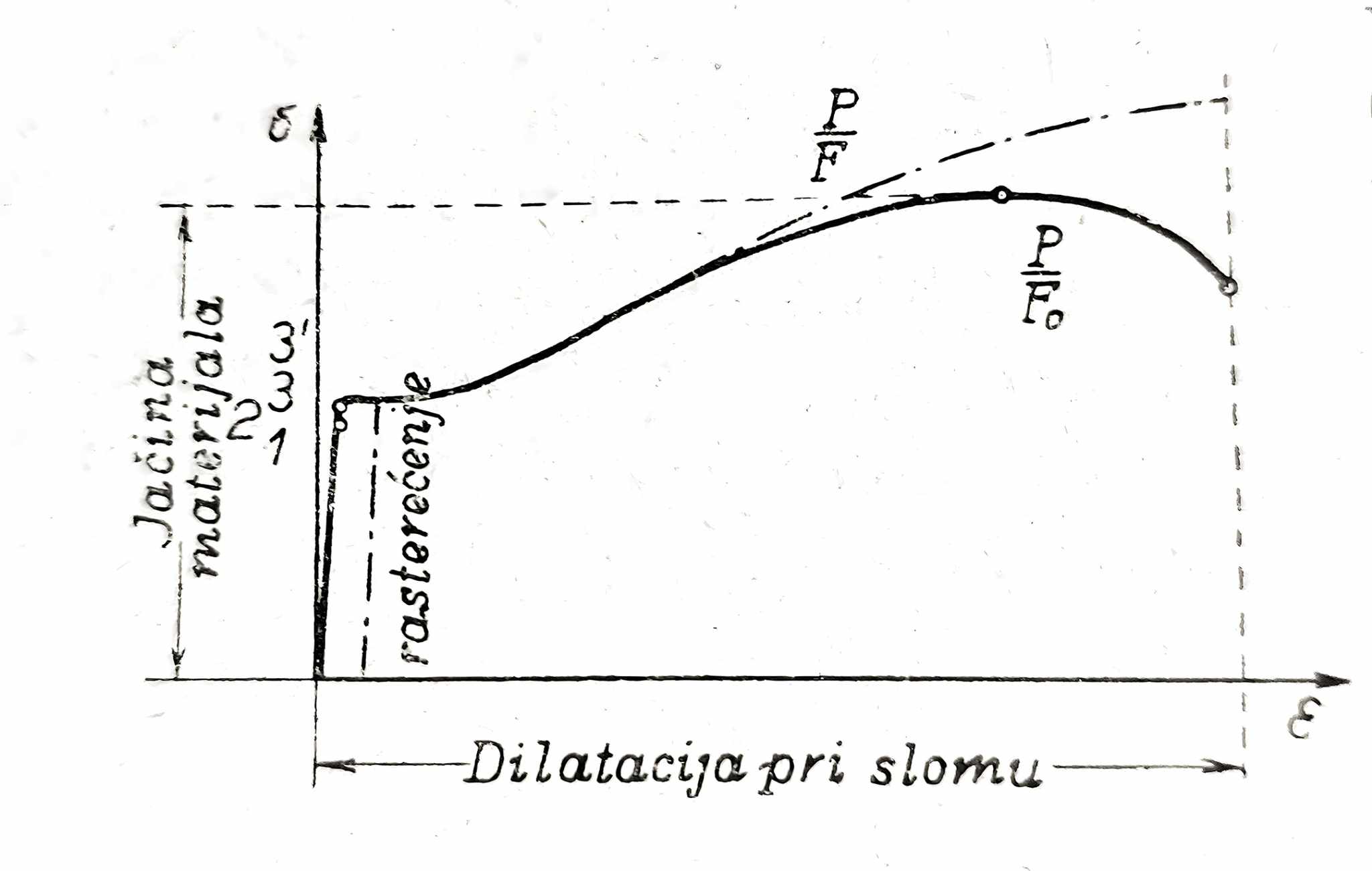
_1= Proportional limit _2 =Elastic limit 3 =Lower yield limit 3’= Upper yield limit
At first the strain is very small and proportional to the stress, as required by Hooke’s law. From a certain stress onward proportionality ceases and the strain increases more rapidly. The exact position of this proportional limit can hardly be determined. The more accurate the measurement, the lower it is obtained. For most materials it lies at δ=0, and Hooke’s law then represents only the first approximation to elastic behavior, the first term in the Taylor series expansion of the function ℇ=ℇ (δ) in the vicinity of the coordinate origin. If the rod is unloaded, it can be observed that, when the stress was not too high, the deformation also disappears in accordance with Hooke’s law. But even this changes if a certain stress is exceeded that lies near the proportional limit, the so-called elastic limit; then the total deformation consists of an elastic (recoverable) and an inelastic (permanent) part. Even the elastic limit cannot be determined exactly; it lies the lower the greater the measurement accuracy.
However, since it has great technical significance, because it represents the limit of importance in almost all calculations in strength of materials, and at the same time the limit at which the first permanent damages occur, it is sharply defined for specimen testing by an adopted convention, so, for example, as the 0,2% limit is designated the stress at which permanent dilation reaches 0,2%.
Immediately after the elastic limit is exceeded, the deformation increases sharply and can be observed with the naked eye; at an almost constant stress the bar elongates continuously. This stress is called the yield limit.
In hydraulic material-testing machines, after the onset of yielding one can also observe a more or less pronounced drop in stress, as indicated in the graph by the dashed curve; the maximum is then called the upper yield point, while the constant yield stress that follows is the lower yield point.
After a certain elongation is reached, which is almost completely inelastic, the stress begins to rise again and the material strain-hardens. In this loading range, a noticeable reduction in the cross-section of the bar occurs due to (inelastic) lateral contraction, and the further course of the stress-strain diagram depends primarily on whether, in calculating the stress, the tensile force P acting on the bar is divided by the original cross-section Fo or the current cross-section F. For technical purposes, the stress P/F is of interest. This stress reaches a maximum, which is called the material strength, and once that maximum is exceeded, the bar narrows sharply at one point and breaks. The “true stress” P/F increases until failure.
The behavior of other metals differs in many respects from that described here. Yielding is often not pronounced, and hardening begins immediately after the elastic limit is exceeded.
In brittle materials (stone, glass, concrete), inelastic deformations are generally small, and failure occurs already at small elongation. The total elongation the material undergoes up to failure is a measure of the ductility (opposite: brittleness) of the material, and for steel it is precisely specified in the technical requirements. However, since immediately before failure further deformation is concentrated around the necked section, a different value of elongation at fracture is obtained depending on whether a larger or smaller part of the bar is taken as the gauge length, so that in order to obtain unambiguous and mutually comparable results, a certain convention must be adopted in advance. Elongation at fracture is usually measured by marking the gauge length l = 10 d on a round bar of diameter d before the test and calculating the elongation at fracture ℇSl = ∆1/1 from its extension ∆l.
If it is necessary to test bars of a different cross-section, the gauge length is determined according to the diameter of a circular cylindrical bar that has the same cross-sectional area.