Important Warning: This is a historical archival text, not a contemporary design, construction, or safety instruction. Descriptions of measurements, markings, tooling, forces and loads do not replace valid standards, calculation, technical documentation or the work of a qualified expert.
This text is not part of the current offer of Savo Kusić, which is focused on windows, doors and associated solutions.
Introductory technical course
This blog is primarily intended for non-experts, so we will try to avoid deep theoretical considerations, and we will give practical advice and applicable solutions. However, there are some knowledges that, although they belong to theoretical technical sciences, cannot be avoided. Especially because they are closely related to practice and have great importance. Simply, they are building a “primary school” of technical sciences. Among them, measurement is the most important, and the term “geometer” comes from here (referring to a specialist who knows how to accurately measure the surface of the land).
The reader will repeatedly encounter the warning:
measure three times,
cut once!
Accurate and successful work without applying the previous rule can only happen by chance.
The basic condition for accurate measurement is a good knowledge of the measuring equipment, its most appropriate choice and application, if any, or its adequate replacement by another one (picture 1).

FIGURE 1
For measuring smaller lengths, a folding tape measure is most commonly used (Figure 1a). It is made of wood or metal. When measuring larger, longer materials, the measurement must be performed carefully, because insufficient leveling (opening) of certain parts of the meter results in a shorter measurement.
A modified form of meter is a steel measuring tape (Figure 1b). It has the advantage that one end is bent at an angle of 90°, so it can be hooked at the end of the measured section and thus only one person can measure lengths of 1-2 meters.
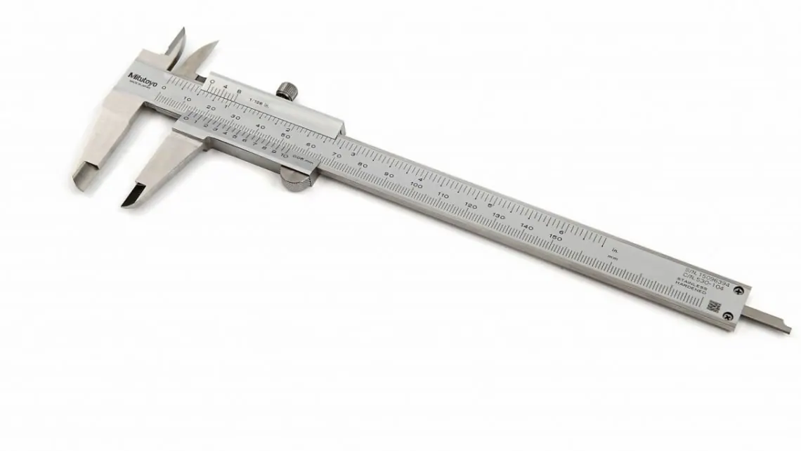
For more accurate measurements, we must use a caliper (Figure 1c). It can be used to measure external, internal and depth measurements up to several decimeters. A vernier (moving scale) allows him to measure with an accuracy of tenths of a millimeter. It has nine major millimeter divisions. At the zero division of the vernier, we read whole millimeters, and at the point where the divisions on the vernier coincide (or are closest) to one of the millimeter divisions, the corresponding tenths of a millimeter.
A micrometer is used for very accurate measurements (Figure 1d). We place the object we want to measure between the hard jaws of the measuring probes of the micrometer and turn the micrometer drum until the measuring probes lightly press against the surface of the object. Then on the linear division on the spindle we read (still visible) values of millimeters and on the vernier the hundredths of a millimeter.
Almost the same importance as the measuring instruments are also the instruments used for fixing or control (picture 2). The most important among them is the angle - winkle (picture 2e). This instrument is shaped like the letter L, ie. the vertical part is attached to the base at a right angle. From time to time it is necessary to check the accuracy of the right angle. It is made from both wood and metal. Its base is wider, and it is placed as a ruler for the edge of the measured object.

FIGURE 2
The adjustable protractor, an instrument used to measure slopes and to control angles (Figure 2f) is also an important tool. With it, “angles” can be transmitted, and with a protractor placed next to this instrument, angle values can be measured. The tip of the tongue of this instrument is precisely machined at an angle of 45 degrees, so it can easily adjust the most used half of the right angle. It can also be used to measure depth and width.
A metal “six” (picture 1g) ruler is used to accurately measure the length, which has the advantage that the fixed length can be applied several times. This is why it is also called a scale compass. When a longer measure needs to be divided into several smaller sections, it is the best instrument.
A compass transmitter for fixing external measurements is similar (Fig. 1h). For measuring and fixing internal measures, i.e. opening is served by the same compass, only fully open (picture 1i). A parallel ruler is used for measuring, applying and marking lengths (Fig. 2j). Like the angle, it can be clamped to the workpiece. By pulling out and fixing the tab to the desired measurement with a marking pin, a parallel line can be drawn.
Finally, it is very important to have a steel ruler in addition to a wooden or plastic ruler (it cannot be cut with a knife, for example, because there is a risk of cutting the ruler), a marking needle and a punch when working with metal, i.e. Kirner.
Making a multipurpose measuring tool
These are only the most important measuring instruments, but if we have them, we will not have unfinished business due to the lack of measuring instruments. If we don’t have the possibility to get so many measuring instruments, we will make a simple and inexpensive universal measuring tool, which can be used to perform seven measuring operations (picture 3).

FIGURE 3
We need to get one thicker protractor up to 360° made of plexiglass (celluloid) and one ruler made of the same material. Starting from the bottom corner -90° (270°) measure 45° on both sides, after which a segment should be cut from the measured sides to the center of the protractor. In the middle of the cutout obtained in this way, we stick a ruler that now divides the angle of 90° into two equal parts and makes it suitable for measuring the angle of 45°. Previously, on the right side of the protractor, we made a small cutout with an angle of 140°.
The schedule of manufacturing operations is as follows: 1. We cut a 2x45° segment from the square. 2. We set the edge of the ruler on the side of the zero division so that it coincides with the center of the protractor. 3. We cut the square to the full length on the ruler. 4. We glue the ruler to the protractor. 5. We cut a section of 140°. 6. Let’s drill the holes. 7. Sharpen the end of the ruler to 15°.
Sharpen the end of the ruler at larger multiple centimeter values at an angle of 15°. We cut out the middle in the form of a wedge and on one side we make a millimeter division to measure the diameter. Or, to control the diameter of the drill we drill holes on the ruler (eg 2,3,4,5 mm etc.). The edge of the ruler, on the side of the beginning of the centimeter division, should be placed in the center of the protractor. At the place of the 45° cut from the protractor, we cut off a part so that the cutting line coincides with the entire division on the ruler. After this, just stick the ruler to the protractor and the universal measuring tool is ready.
Seven different jobs can be done with this little tool. In addition to marking the tops of laths, boards, cardboard, etc. at an angle of 45°, we can mark with the end of the ruler at an angle of 15°. The task of the 180° protractor is to determine angles. By rotating the tool, we get a min ruler. The notch of 140° on the side serves to control the inclination of the tips of the drill bits. The angle of 140° is larger than the average inclination angle of the drill tips, so that smaller angles can be approximated when measuring.
The aid can also be used to find the center of a circular object. By turning 90-120°, and dragging the 2-3 line, it is possible to determine the center. The centimeter division on the straight ruler can independently be used to measure lengths, while the millimeter division in the middle cutout (or holes with increasing diameter) is used to measure the diameter of rolling materials.
About marking
The line drawn with a pencil or needle must always be to the measurement, or slightly to the side of the piece being cut. The part that falls off needs to be scratched. To mark wood, we use a special flat pencil for wood, which should be sharpened but not sharpened. A ballpoint pen can also be used.
When marking a point rather than a line, the marking is done with two criss-cross lines. The measurement lines drawn on the workpiece should be slightly longer than the required value and where the two measurements touch, intersect each other, the lines cross.
Finally, here is, again, the main rule: measure three times…
Let’s also get to know the template for cutting at an angle (picture 2k) which allows the slats to be cut or cut at an angle of 15°, 30°, 45° and 60° without any measurement. It is an open box-like tool that has grooves on the sides. The sides are made of hardwood where, after very accurate marking, grooves are cut at the angles that are most used. The workpiece is placed in the slot in the middle of the tool, fixed and cut without difficulty at the desired angle.
Three data worth noting: 1 English inch, sol=2,54 cm; 1 ft=30 cm; 1 pound=450 g.
About loads
When we already know what we want to make, and we know how to determine the measurements, we should also think about what kind of load the item we are making will have to withstand. That is why it is necessary to familiarize ourselves with the names of the basic load cases. All the more so, as in most cases the choice of material depends on the load (picture 4).

FIGURE 4
The pressure (Figure 4a) can be static, i.e. constant (such as, for example, acting on the supporting columns that hold the roof structure of the house) or dynamic, which originates from the action of forces during movement (eg, the action of a hammer on a rivet, or the action of two cars on each other during a collision).
Pulling out, tearing (Figure 4b) is the opposite effect of pressure. A classic example of this is the appearance of a force in a rope when it is tensioned. The same is the case with the screw that holds the gate hardware, whose nut we tighten more and more with the open-end wrench.
Twisting (Figure 4c) acts on a gate key when we turn it in a lock, or a screwdriver when we drive a wood screw into hardwood. Twisting of the screw can often be observed under excessive load.
Buckling (Figure 4d). An obvious example of buckling is the sword buckling of a fencer when the tip of the sword hits the opponent’s armor. Buckling usually occurs when a thin long bar is loaded at the ends, e.g. the case of supporting beams of the roof structure, if they are thin beams (the same force acts on the lower side of the beam as on the upper side). It is important, after all, to note this: one often has the impression that the forces act only from one direction, but due to the resistance of the support, they actually act from the other side as well. If, for example, we tie one end of the rope to a tree, and the other end is pulled by one team, such a force acts on the rope as if, instead of the tree, there is another team pulling the rope.
Bending (picture 5e). When a force acts on one end of a horizontal beam whose other end is clamped, it causes a bending. Bending of the beam can be greatly reduced by choosing a suitable cross-sectional profile. We can often see that sheet metal bending can only be done if one end is tightly clamped and the other end is applied with a bending force. Figure 6 shows the buckling and bending resistance of various wood and metal profiles. The lowest resistance is shown by the upper, flat batten, and the highest by the metal pipe and wooden beam, made according to the picture below.

FIGURE 6
Shear (Figure 5f). The most famous example of shearing is cutting sheet metal with scissors. And rivets are exposed to shear that can cut them when the riveted plates move against each other under the influence of tensile or compressive forces. It is important to note the static and dynamic loading. One is the load if we stand carefully on the hook with our 70 kg, and the other when we jump onto it from a height of 2 meters. Elements exposed to dynamic loading must be dimensioned much more strongly.

FIGURE 5
Valid standards, accurate material data, load calculation and verification by a qualified expert are relevant for every modern application. The historical examples from this text are not a proof of load-bearing capacity or an instruction for construction.