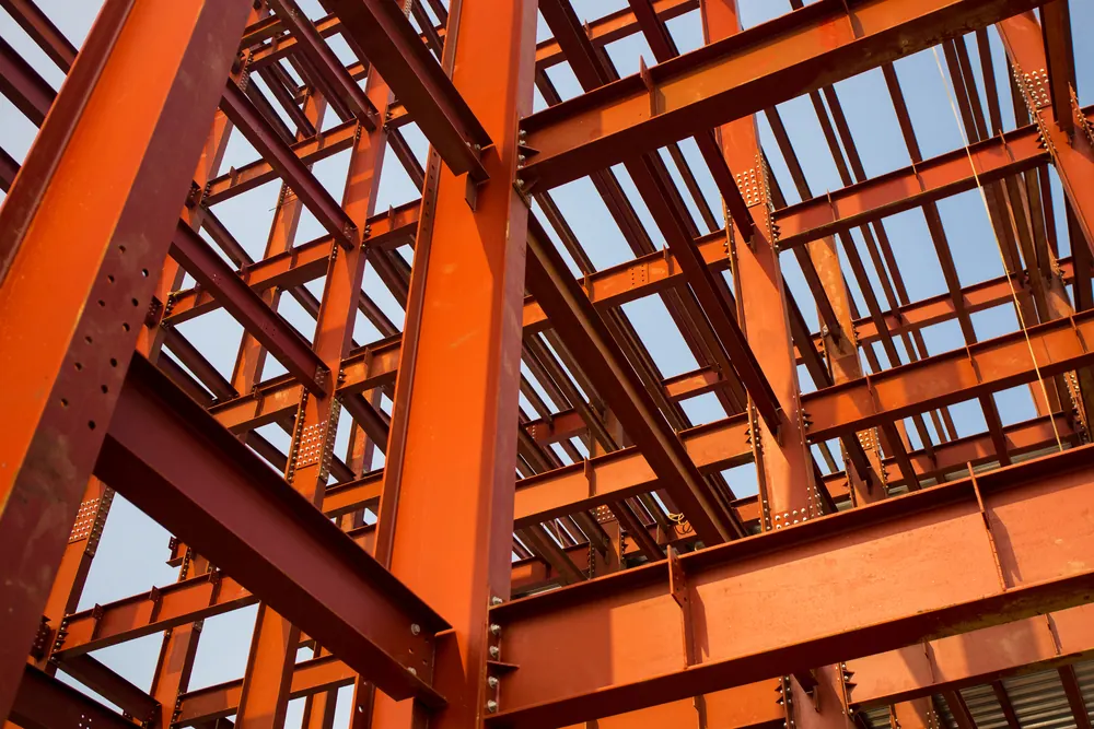
Extensions are connections used for lengthening or increasing. Extensions are needed, for example, because the available rolled sheet lengths or widths are not sufficient; during installation they are required because of the dimensional and weight limitations of the individual elements being transported. Cover plates are the sheets that bridge a discontinuity in an extension. All other connections, especially those between truss bars in different directions and supports in different planes, are referred to as attachments.
In conventional splices, the splice straps and splice rivets are dimensioned according to the full force. Therefore, in a normal splice it is not required that the splice surfaces be in contact.
The main field of application of tension and compression members (these are straight members loaded mainly by normal forces) is trusses. The considerations in this section disregard the danger of buckling of compression members. First, static strength will be considered.
Deduction for holes in tension members
Load-bearing capacity: The stress state in a tension member is significantly locally altered by holes/openings. In the proportional range, the stress distribution corresponds to the weakened section (fig. 1). The maximum longitudinal stress in a rectangular bar according to A. Henning is:
maxσ = σm*[3-(d/b) + 0,8(d/b)2]

Fig. 1 - Longitudinal and transverse stresses in a drilled rod a) according to A. Henning; b) according to M. Rudeloff
In the limiting case d/b = 0 of very wide strips, this gives maxσ = 3σm, and for the case shown in fig. 1a, d/b = 1/3 gives maxσ = 2,42 σm. Besides longitudinal stress, there are also transverse and shear stresses. The greatest stress is at the hole boundary. There the first permanent deformations appear, i.e. the stress peaks are broken down and stress equalization occurs across the section. Noticeable permanent deformations in the region of the holes arise only when the mean stress σm in the weakened section exceeds the yield limit σFO. The total elongation of the bar at SF = Fm * σF is only slightly greater than that of a bar without holes. (Fm is the area of the weakest cross-section)
In tensile tests with riveted bars, fracture always occurs in the weakened sections. The load at fracture is, under usual conditions, sufficiently accurately SB = Fn * σB. Fracture tests on tensioned bars with open holes showed fracture patterns as in fig. 2.

Fig. 2 - Fracture patterns of tension members
Experiments with riveted joints have shown that splices with straps and a single row of rivets have lower resistance than splices with several rows of rivets one behind the other. Accordingly, the average fracture stress σB in the net section was:

Design procedure for tension members: According to the usual calculation method, the average tensile stress must satisfy σm = S/Fm ≤ allowable σ in all relevant cross-sections Fm. The deduction of holes is determined for the net section with the largest number of holes, and it may happen that a broken section with more holes gives a smaller value of Fm (fig. 2). In this sense, for rolled sections Fm is calculated including the gross development. The same approach is used for composite sections.
The ratio Fm/F usually lies between 0,8 and 0,9, i.e. the hole deduction ΔF = F – Fm amounts to 10% to 20% of the total cross-section F of the bar. In large structures, ΔF has a significant effect on weight, so it is worthwhile to find cross-sections with a smaller hole deduction.
Deformations: The elastic elongation of tension members with holes is only slightly greater than that of comparable unperforated members. The total elongation of splice joints is almost as great as that of spliced plates. Therefore, for calculating deformations of steel structures, it is sufficient to determine the elastic elongations of unweakened members using the E and F values. The safety against yielding is greater in weakened members than, for example, in compression members.
Distribution of forces in rivets

Fig. 3
The distribution of force S in the bar among the individual rivets of the joint depends on its elastic properties; it is “statically indeterminate.” In the case of fig. 3, the distribution of N1, N2, … depends on the deformation of the rivets and the connected plates; it changes with the ratio Ftie/Fbar. For Ftie ≠ Fbar, the end forces in the rivets are no longer equally large (fig. 50a). As the ratio Ftie/Fbar decreases, Nn becomes smaller, N1 approaches S. Joining strips of very different thicknesses (fig. 4b) is not appropriate because of the overloading of the first rivet.
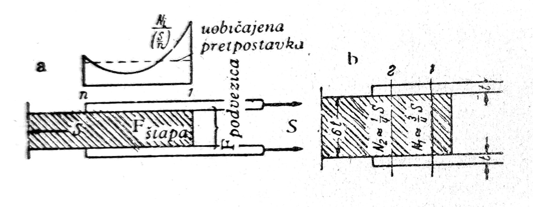
Fig. 4 - Loading of the rivets for Fštap > Fpodvezice
The slats and tie rods are rigid, only the rivets are flexible (fig. 5a). Then all rivets undergo the same bending, and all forces in the rivets must be equal.
The rivets are rigid, only the plates and tie rods are elastic (fig. 5b). Since the elongations in the bar and tie rods between the first and the last rivet must be equal, it follows that N2 = N3 = … = Nn-1 = 0, except N1 = S * x1.

Fig. 5
The actual distribution of forces lies between these limiting cases. As the load increases, permanent deformation first appears in the end rivets, the most heavily loaded rivets are relieved, and the force distribution becomes more uniform. After larger deformations appear, the force distribution approaches the case where the strips and tie members are rigid, i.e. the forces in the rivets are all nearly equal, in the case where the shear of the rivets is decisive.
Failure load: The method of riveting the rivets has almost no influence on τBV. The shear strength τBV of the joint is practically independent of the number of rivets, their arrangement, or the form of the riveted joint; the failure load corresponds, to a good approximation, to uniform loading of all rivets. The same statements also apply, incidentally, to ordinary bolted joints, from which it can be concluded that resistance to slipping has no significant influence on load-bearing capacity.
Sizing: In steel structures and centrally loaded bars, calculation is made by uniform distribution, i.e. N = S/n per rivet. Since in long joints the first rivets are already overloaded quite early, more than 6 rivets one after another should, if possible, be avoided.
Slip resistance: Slip in joints occurs already at a relatively small load. Slip resistance depends primarily on the clamping force, which varies with many influences. It is neglected in the design of riveted joints and the bolt types commonly used up to now. Attention is drawn to connections using high-strength bolts.
Distribution of forces in rivets across the width: With equal rivet spacing perpendicular to the direction of the force (Fig. 6a), each rivet is assigned equally wide strips a of cross-section, so in the first approximation the forces in the rivets N = a t σ are equally large. The distribution with unequal rivet spacing is statically indeterminate; for the case in Fig. 6b it follows the lever law.

Fig. 6
Tension member
Extension: Extension with symmetrical tie rods (fig. 3 and 4). The force S in the bar at the joint must be carried only by the tie rod. The splice at the joint should likewise be dimensioned according to S, because it must transfer the entire force from the extended bar into the tie rods.
Splices with one-sided cover plates are associated with considerable additional bending stresses in the connected sheets, cover plates and rivets. Due to the large deformations, one-sided covering of splices is applied only when (fig. 7) the bar is rigid in bending or when it is laterally restrained so that it cannot bend.
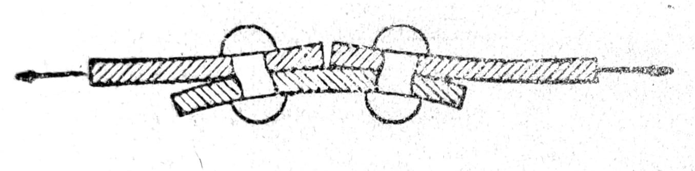
Fig. 7
Indirect jointing – When straps cannot lie directly on the spliced sheets, the rivets and sheets are subjected to considerably greater bending stresses. Therefore, according to the number m of interlayers, a larger number n’ of rivets is chosen than the number n in direct covering of the joints.
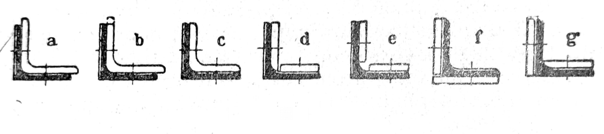
Fig. 8
In composite cross-sections, the tie plates are arranged so as to avoid local stress concentrations; therefore, the individual areas of the tie plates are determined according to the area of the part of the cross-section they cover, preferably while maintaining the position of the centroid. Tie-plate area distributions that deviate from this are associated with changes in the stress distribution. Figure 9 shows the extension of a single-web member, and fig. 10 shows a two-part member with 4 vertical plates and one face between the angle sections.

Fig. 9
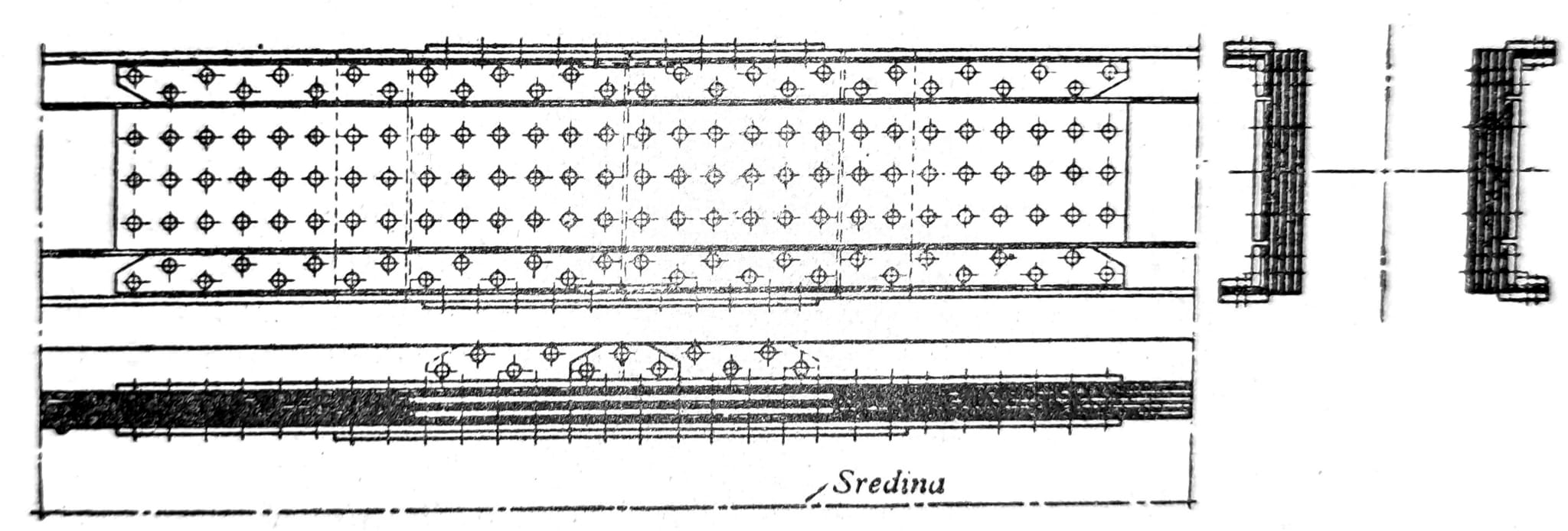
Fig. 10
Connection: For connections of tension members, basically the same relationships apply as for splices. Tests have shown the great advantage of symmetrical force introduction. With a one-sided connection, strong bending occurs in the longitudinal and transverse directions (fig. 11). Despite considerable additional bending stresses, one-sidedly connected L and C members can be utilized almost completely. The load-bearing capacity of a connection may drop to half if measures are not taken to equalize the additional bending moments.
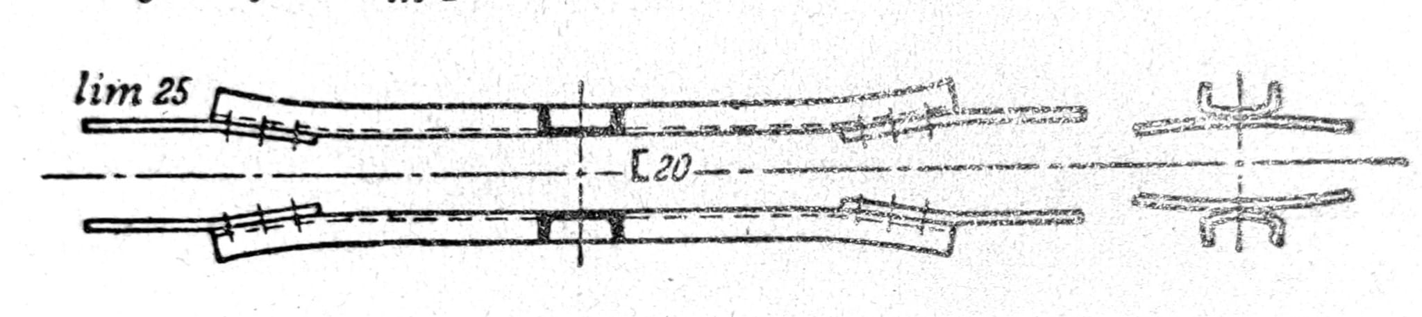
Fig. 11
For covering splices, node plates should not be used; special cover plates should be provided for this purpose. The connection to the node plate is facilitated when the greater part of the bar cross-section lies in the plane of the node plate.

Fig. 12 - Connections with and without a connection angle bracket
Compressed member
The same principles apply to the splicing and connection of compressed bars as to tensioned bars; in both cases the total force is transferred by rivets and clamps, i.e. according to the full area F of the bar, Fclamp and Fs, or Fl, are dimensioned. As a rule, the splice surfaces are not matched. In steel structures in building construction, in columns extending through several stories and loaded only in compression, the possibility of passing through with less overlap of splices is used. The load-bearing capacity of compressed bars is exhausted, if instability does not occur earlier, at the latest upon reaching the yield limit, because then large deformations occur and the bar buckles laterally. Holes filled with rivets do not have any detectable influence in this respect on the behavior of the bar.
Fatigue strength of riveted joints
For the fatigue strength of riveted joints, the decisive factors are primarily the stress peaks that occur at the holes. Fatigue strength is significantly reduced by the holes themselves. Bars with open holes fracture in fatigue tests under tension at the weakened cross-sections, and the fatigue fracture begins with cracks at the edge of the hole, which continually extend farther through the cross-section. Therefore smooth holes are of particular importance. Fig. 13 shows the fatigue strength of flat bars in various classes (on the right is the higher steel class). At higher prior loads σu, both materials withstand fatigue strengths σDz above the yield point. The stress amplitude is approximately the same for both classes.

Fig. 13 - Fatigue strength σDz
For alternating tension and compression loading of riveted joints, essentially similar relationships apply as for unidirectional loading. It is worth noting that the stress amplitude under alternating loading is about 1,5 times greater (fig. 14), but that rivets under this loading are evidently much more endangered than under unidirectional loading.

Fig. 14 - Fatigue strength in tension of riveted joints