Important technical note: This is an archival educational text, not a current design specification, structural calculation or fabrication and erection instruction. The design and construction of steel structures must follow current regulations and standards, documents prepared by an authorised engineer, manufacturer documentation, inspection of materials and welded or mechanical connections, and prescribed safety measures.
The design and construction of steel structures is not part of Savo Kusić’s current public offering. The present manufacturing focus is timber windows, timber–aluminium windows and custom-made doors.
In steel structures, bars, beams, vessels, plate and shell elements, and similar members are assembled from rolled sections. Connections must join the individual sections so that they form structural components acting as a single unit. This is achieved only when the connections can safely transfer the forces that arise between the individual parts. Where only compression occurs between two parts, the force is transferred by direct contact between the fastener and the element. In addition to rigid connections, movable connections permit certain movements (hinges, central pins, sliding devices, bearings, etc.).
Rivets
Only the basics are given here because rivets are now rarely used and have largely been replaced by bolts. Rivets are pin-like fasteners, similar to nails, placed in holes through the parts to be joined and then riveted. Unformed rivets (fig. 1) are made from rolled round steel. In steel structures, they were driven while heated to a bright-red state. During riveting, the existing head of the unformed rivet is firmly supported with a suitable tool. The closing head is shaped with a hammer, usually pneumatically powered, only after the rivet shank has fully filled the hole. For a sound riveted connection, the shank must completely fill the holes. The rivet diameter is 1mm smaller than the hole diameter, and the shank must be compressed by pressure or blows before the closing head is formed.
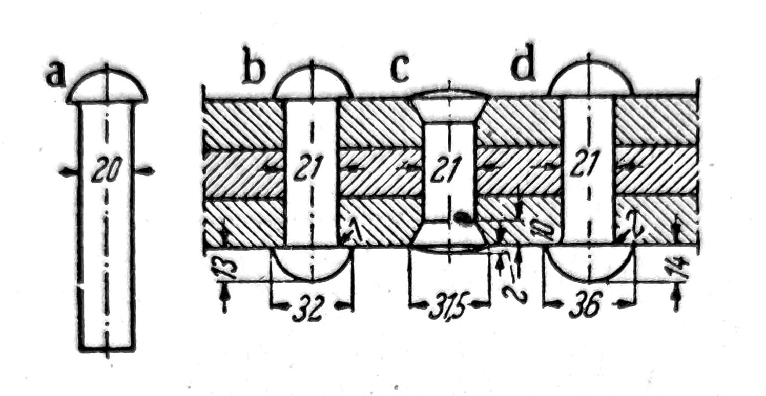
Sl. 1 - a) Raw rivet; b) Rivet with semicircular head; c) Rivet with countersunk head; d) Rivet with semicircular head for boilers
Stress and strength of individual rivets (static)
Connections acting in shear (fig. 2) form the most important area of application for rivets in steel structures. According to the number of shear planes through the rivet shank, single-shear, double-shear and multiple-shear connections are distinguished (fig. 3). The connection shown in fig. 4 (a double-shear connection) has a symmetrical stress state.
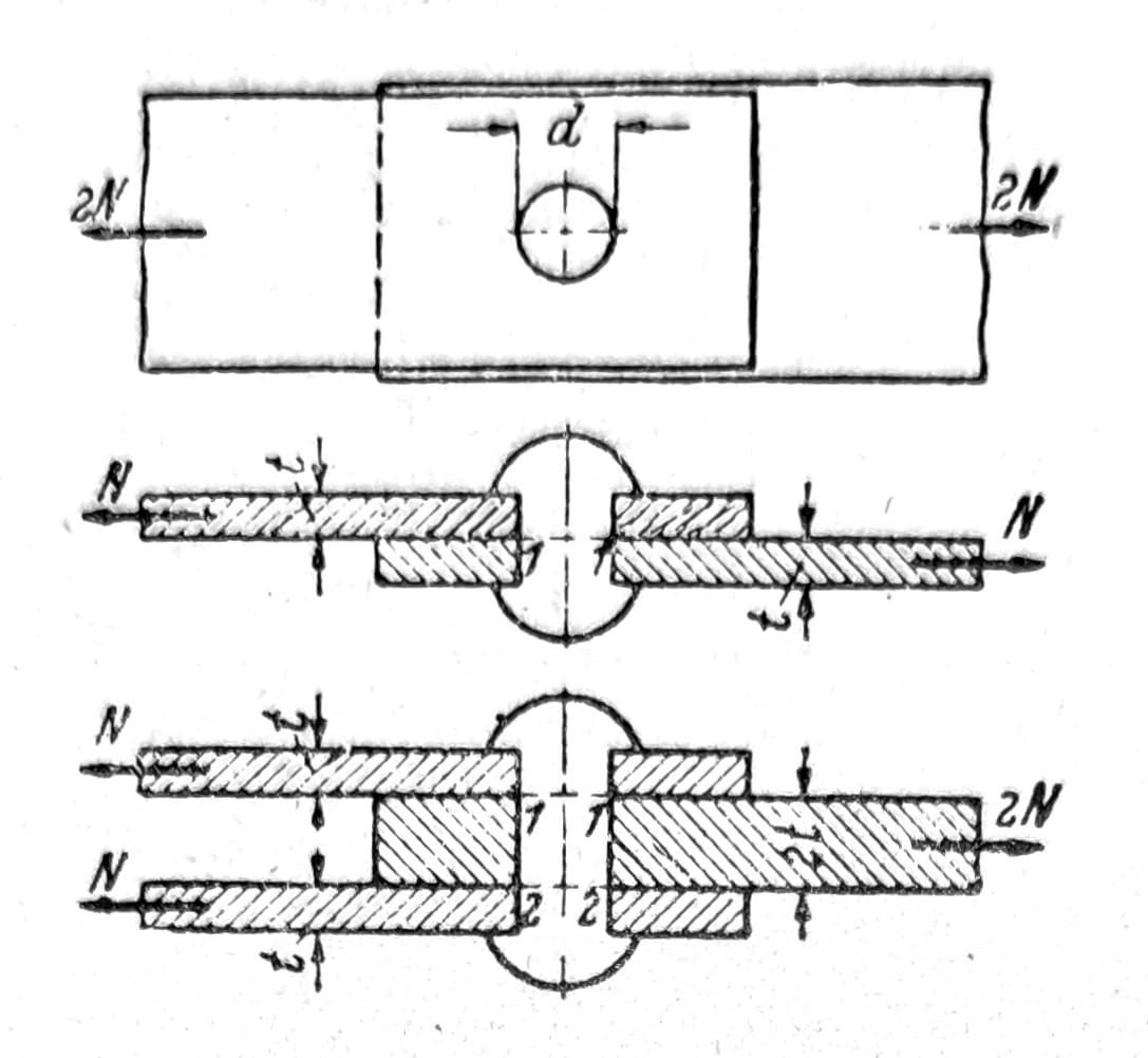
Sl. 2
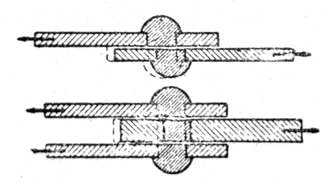
Sl. 3 - One-piece and two-piece connection
The bearing pressures between the rivet shank and the wall of the hole depend on the rivet diameter and the dimensions of the connected parts; their distribution is shown in fig. 4a. For practical calculation, a uniform stress distribution through the plate thickness is assumed (fig. 4b). The stress distribution around the circumference of the rivet shank is shown in fig. 4c. For sizing, a uniform distribution over the diameter is assumed according to fig. 4d. The average value σlm is the bearing stress on the hole wall.

Sl. 4 - Voltages per hole envelope; a) and c) real; b) and d) usual calculation assumptions
The usual calculation of rivets
The shear strength depends primarily on the material of the rivets. When evaluating the test results, it should be kept in mind that the material of the rivets is different from that from which the sheets are joined and that the strength of the rivet material is increased by riveting the rivets.
The compressive strength along the hole envelope, as the highest load value, is not as clearly expressed as the shear strength. When the distance e from the end of the sheet is not too great, the rivets tear it; Fig. 5 shows breakdown images. The crushing stress on the hole envelope, required for shearing the ends of the sheets, can for e < 2,5d be represented by the form σlB = σB e/d. The width b has no noticeable effect on the crushing strength of the hole envelope, σB is the tearing strength of the joined sheets.
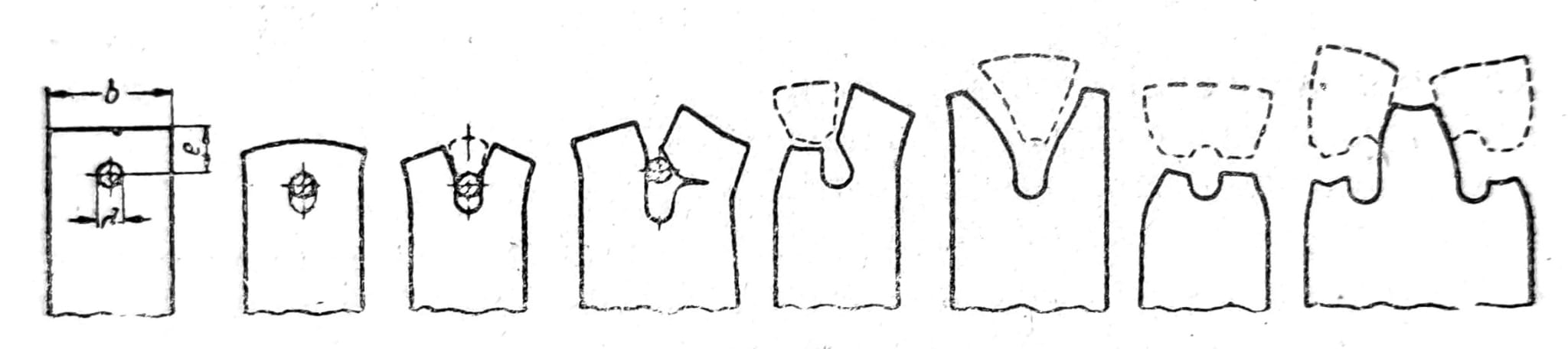
Sl. 5 - Types of fractures
Historical rivet rules
Rivet spacing. The centre-to-centre spacing e has a lower limit because of riveting access, stress concentrations and the reduction in resistance caused by holes. The maximum spacing is also limited so that connected plates do not separate and admit corrosion, or buckle under compression. The maximum distance depends on plate thickness t. Within certain limits, customary rivet spacings differ between railway bridges and other steel structures. The edge distance e1 lies in the direction of the force, while e2 is perpendicular to it.

Position of rivets. The rivets are mostly arranged in regular rivet patterns and placed in straight lines behind each other. For wider cross-sections, more rows of rivets are required (fig. 6), whereby table 1 should be followed. For internal structural rivets of wide tensioned rods, e can be increased up to double the values from table 1.
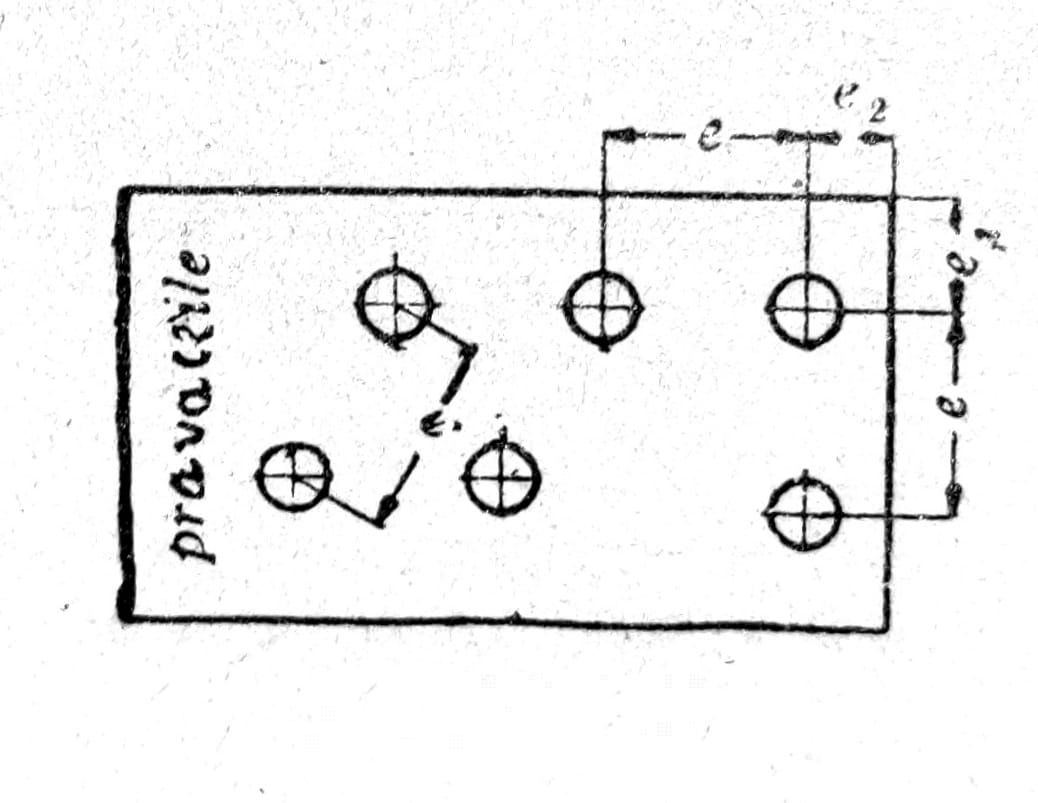
Sl. 6
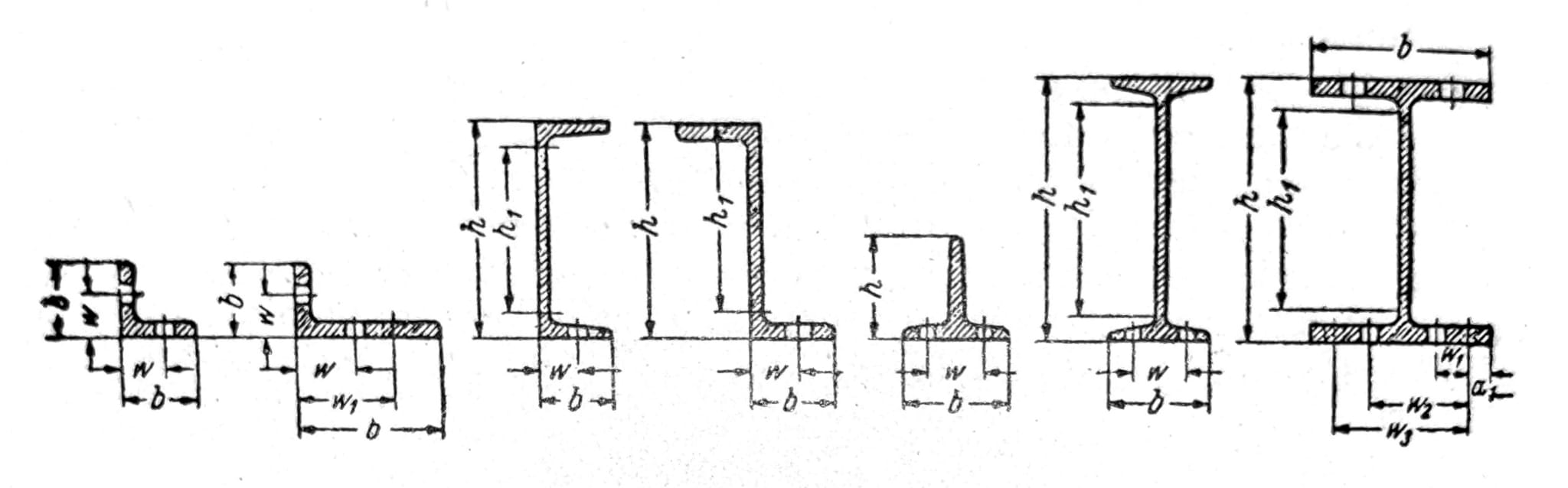
Sl. 7 - Example of rivets for profiled steel
Bolts and pins
Screws are almost always used in constructions where it is necessary to secure the connection. Bolts made of high-quality material should transmit forces by friction, while the shear strength and compressive stresses on the plug shell do not contribute significantly. In steel structures, screws with metric threads are used. The rules for applying screws correspond to those for rivets of the same hole diameter d. However, the smallest distance must not be less than e = 3,5d, preferably 4d. Other distances, roots and linear measurements are the same as for rivets. The bolts must be further offset from each other than the rivets, due to the greater need for space for the nuts and bolt wrench.
For steel constructions, mainly the following forms are considered:
Raw hex screws: have a hex nut and a washer Thread diameter d = 10 to 33 mm with hole diameters d1 = 11 to 34 mm. These screws are machined only in the threads, so a gap of 0,5 to 2 mm between the body and the hole should be calculated. Care must be taken with higher forces because bolted connections often show considerable deformation.

Sl. 8 - Screw
Slotted screws: their dimensions correspond to the raw hex screws, but they have a precisely cylindrical machined body so that they fill the hole well. Fitted screws replace raw ones when larger forces need to be transmitted or when movements in connections need to remain within small limits.
Backing plates: screws are applied with backing plates. The thickness of the plate depends on the size of the screw used.
Markings: markings, hole and screw sizes are given in the following table:

Sl. 9 - Screw marks
Static loading of individual bolts
Shear connections: The stress state in bolted connections is similar to that in riveted connections. When dimensioning, it is calculated with the average values of the shear stress τm and the pressure on the casing of the hole σlm. It is known that the pressure on the casing of the hole increases greatly when the threads enter the hole, which should therefore be avoided.
The frictional resistance in normal bolted connections is lower than in riveted fittings because only relatively small tightening forces can be achieved when tightening the nuts. Tightening too much will damage the threads. It refers to the high-value screws that make the friction resistance in the connections crucial for their behavior.
The shear strength of fitted cylindrical plugs is the same as that of rivets. A static tear test cannot, under normal circumstances, determine any difference between fitted plugs and rivets in terms of compressive strength per hole envelope. Under fatigue loading, the proportionally lower frictional resistance is the cause of significantly different behavior of bolted connections.
Raw screws have up to 20% lower resistance in shear-loaded connections due to the gap between the hole and the screw body. For this reason, the permissible stresses for raw screws are lower than for fitted ones. For sizing, the actual body diameter d should be taken.
Joint pins
Joint plugs provide a tension- and pressure-resistant connection where the joined elements can rotate. Application at the joints of Gerber supports, suspended belts of chain suspension bridges, connections of tensioned rods in the form of joints, etc. Grids with connections in knots to the joint, so-called. bridges with corks are almost not built anymore. High frictional forces, which occur on the plugs, prevent movements, while mutual rotation is achieved only with higher torques.

Sl. 10 - Caps, a) cap with screw; b) cork with split; c) plug of a suspension bridge
The stress state in the plug is generally the same as for riveted connections. The plugs are therefore dimensioned according to the mean shear stress τm and the average compressive stress per hole envelope σlm. Since the plugs must be easily rotated, however, σlm is taken less. Bending stresses in plugs are mostly insignificant, but can reach considerable magnitudes when the joined sections are highly concentrated.
Current calculation methods, prescribed joint details and project documentation of an authorized expert are used for each real object. This text is preserved as a historical educational resource.