Important safety note: This is an archival educational text from 2017, not a design or current instruction for carrying out construction yourself. Excavations, slopes, retaining walls, paths, steps and ponds can affect the stability of the ground and building and involve risks of falling, burial, injury and drowning. Underground services, drainage, reinforcement, child protection and accessibility should be addressed in accordance with current regulations and the conditions of the specific site. Planning and construction should be entrusted to qualified designers and contractors. The photographs and drawings are illustrative and do not represent confirmed Savo Kusić projects.
Landscaping, garden paths, steps, retaining walls and ponds are not part of the company’s new public offer. The current manufacturing focus is on wooden windows, wood-aluminium windows and made-to-measure doors. For a specific window or door project, you can send a request for quotation.
Planning the use of land
Before arranging the land around a family house or holiday home, the intended use of the space should be determined, taking into account its size, relief, position, soil quality and connection with the surroundings.
The original text suggests distributing the available space according to the household’s needs: for an orchard, vegetable garden, flowers, walking and rest. These uses do not have to be strictly separated. A garden can have an economic role, while remaining an ancillary part of the living space that should be pleasant to spend time in.

Surveying the terrain before preparing a plan.
Surveying tools and procedures
Preparing a shaping plan requires knowledge of the size, position and condition of the surface. The source notes that a site plan shows the horizontal projection of actual dimensions, so sloping land requires allowance for a difference that increases with the angle of the slope.
The historical surveying equipment listed includes a measuring tape, two 2 m measuring rods divided into 10 cm sections, two drawing boards on tripods and two protractors. A large 45° triangular ruler, a celluloid protractor, a movable pointer and a lead weight are described for making an improvised angle-measuring instrument.

Archival drawing 1 — improvised surveying instruments.
For horizontal angles, the drawing board is set level, directions are transferred to paper, and the resulting triangles are measured, drawn to scale and used to calculate the area. Curved plot boundaries can be divided into straight segments.

Archival drawing 2 — measuring the surface area of land.
In the original procedure, the slope is determined using two vertical measuring rods: the horizontal distance and height difference are measured and the gradient is then calculated as a percentage. A straight board is mentioned as a direct aid on the slope.
Height and hard-to-reach distances can be determined by construction from measured angles. To establish a right angle without a protractor, the text gives the classic 3–4–5 relationship: the baseline is 4 m, with arcs of 5 m and 3 m radius drawn from its ends.

Archival drawing 3 — measuring height and slope.
Making terraces and shaping slopes
After surveying and planning, the land is arranged. The aim may be to obtain a larger level area or turn a slope into terraces. The source recommends shaping slopes in the direction of the gradient to move less material.
General slope ratios of 1:2 and 1:1 are given, and 2:1 with appropriate support. A slightly larger initial embankment is mentioned to allow for subsequent settlement. In the text, turf protects a slope against washout and stakes protect it against sliding. A modified shovel that cuts pieces approximately 30 × 30 cm is described for lifting turf.

Archival drawing 4 — lifting and laying turf.
On a loose slope, the source mentions larger stones at the bottom and smaller stones at the top. Stones are placed in prepared beds without being forced into place; if striking is required, a wooden mallet is specified.
For gradients greater than 45°, the text warns that a retaining wall on firm load-bearing ground may be required. For a dry-stone wall, the historical guideline states a base width equal to half the wall height, while the width of the top is one fifth of the base width. The blocks must be stable, with no loosely placed stones.
Concrete walls and stone walls bonded with mortar require drainage. The source describes a channel above the slope and drainage openings at intervals of 1–2 m in solid walls. Without suitable drainage, water can undermine the wall. Low shrubs and grass are mentioned at terrace edges for additional protection of the soil.

Archival drawing 5 — examples of retaining-wall drainage.
Terraces should slow surface runoff after rainfall and retain more water for plants. The source suggests grass strips in the direction of runoff, gentler gradients and channels at terrace edges.
Garden paths
Paths may be intended for pedestrians or vehicles, so their base and finish differ according to the load. The source gives a width of 40 to 100 cm for pedestrian paths; two people can pass one another on a width of 100 cm. The finish does not have to be continuous, so grass can remain between slabs.

Construction begins by setting out the space for the base, edging and surface. The set-out area should be wider than the finished path. The text describes edging made of concrete, stone, brick or plants. For vehicle paths, a base is mentioned only in the strips travelled by the wheels, while the centre may be filled with gravel or slag. The surface should drain water away.

Archival drawing — forms and sections of paths.

Archival drawing 6 — levelling, preparing the bed, laying and compacting slabs.

Archival drawing 7 — shaping a path and draining water.

Archival drawing 8 — examples of bases for a vehicle path.
For longer pedestrian paths, the source suggests a foundation stone for levelling at intervals of 1–2 m. The remaining elements are placed to that level, with a slight gradient for water runoff.

Archival drawing 9 — levelling a path.
Steps in the garden
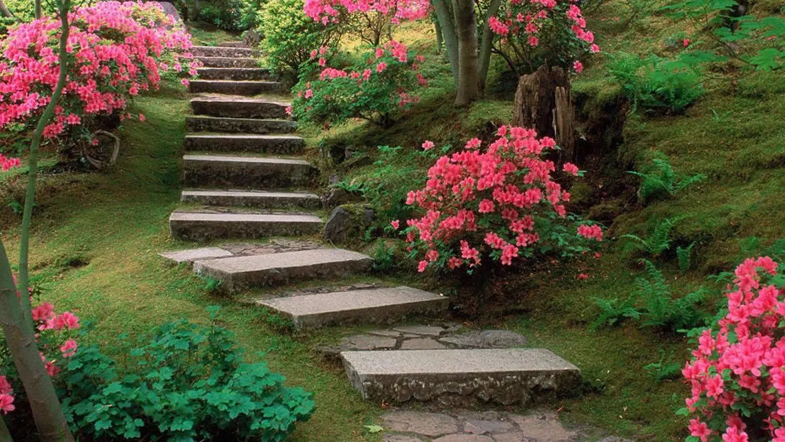
On terraced land, paths and steps often alternate. Level sections should also have a slight gradient, and the number of steps should be reduced to the necessary minimum.
The source describes simple steps made of undressed natural stone, with supports beneath the more heavily loaded front edge. This solution is not intended for steep stairways. As a historical guideline for comfort, a landing is specified after every 8–10 steps. Steps and landings should drain water and comply with the prescribed relationship between riser height and tread depth.
For earthen steps, stronger stakes, boards and slats are mentioned, with a step height of up to 10–12 cm and water drained to the side. A layer of gravel or slag is given for brick steps, while stone steps require flat front and top surfaces and secure fixing to prevent loosening.
Garden ponds
The source describes several historical methods for constructing a small pond. With a lining of compacted clay, the excavation is made 40–50 cm deeper than the desired pond depth and the clay is applied in three layers, each 10–15 cm thick.
On sufficiently firm ground, plastic sheeting is mentioned, with the bed carefully levelled so that pressure does not tear the lining and an earth embankment placed over the edges of the sheet.

For a concrete pond, the source specifies a 10–15 cm layer of concrete with formwork. For larger ponds, reinforcement and 2–3 insulating layers are mentioned, along with a drain and a correctly positioned overflow. Once the concrete has set, the text recommends at least three complete changes of water before plants are introduced, because of substances released from fresh concrete.
Plants that tolerate moisture are suggested around the pond. The source also mentions introducing water fleas of the genus Daphnia as a method then described for limiting stagnant water; this historical claim should not be applied without a current assessment of water quality and pond ecology.
Once the garden work is complete, the original article announces a fence as the next subject. Fences, like the other work described in this archival text, are not part of the company’s current window and door offer.