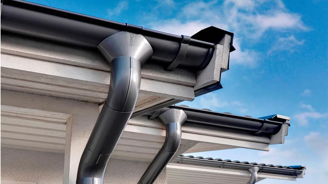
Important safety note: This is an archival educational text from 2017, not a design or current instruction for installing gutters yourself. Work on roofs and ladders, cutting, drilling, riveting, soldering, open flames and solvents involve risks of falling, fire, injury and harmful exposure. Historical materials and coatings mentioned in the text should not be used without checking current regulations and manufacturer instructions. Sizing and work should be entrusted to qualified designers and contractors. The photographs and drawings are illustrative and do not represent confirmed Savo Kusić projects.
Gutters and roofing work are not part of the company’s new public offer. The current manufacturing focus is on wooden windows, wood-aluminium windows and made-to-measure doors. For a specific window or door project, you can send a request for quotation.
Why gutters matter
Gutters are among the last elements installed on a building. When the building budget has already been spent, these apparently less important elements may not be purchased and installed immediately.
A building may look finished without gutters, but roof water then falls directly beside the walls, soaks the ground and reaches the foundation walls. Water splashing from the ground can wet the wall and render above the damp-proof course, leading to signs of damp, falling render and moisture indoors.
Damage or holes in a gutter can cause leaks on nearby surfaces, ceilings and outside walls, with paint and rust marks. The source describes these defects as easier to repair than dampness in foundation walls.
Gutter materials and sizing
The source lists 0.5 mm galvanised steel sheet, less commonly 0.7 mm tinned or aluminium sheet, and plastics. Its sizing rule assumes 1 cm² of gutter cross-section for every 1 m² of roof area.
Flat strips are cut from 1,000 × 2,000 mm sheets without waste. Standard developed widths are 250, 333, 400 and 500 mm, giving gutter designations 25, 33, 40 and 50. The required width is selected from the roof pitch and its horizontal projected area using the source table.
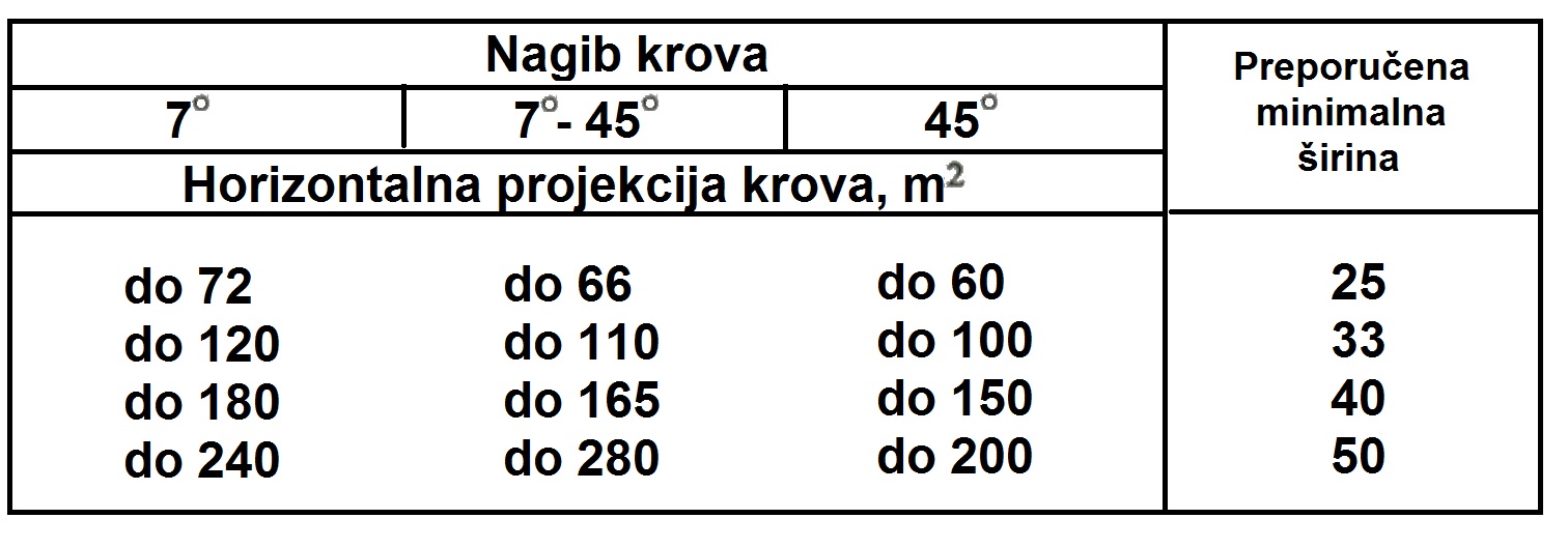
Archival table — recommended minimum gutter width.
Elbows can be bought as finished elements. End caps for mono-pitch and gable roofs are formed from tinned or galvanised sheet and attached by soldering or by soldering and riveting.
For gutter designations 25, 33, 40 and 50, the source table gives 6, 7, 9 and 13 rivets respectively.

Archival table — required number of rivets.
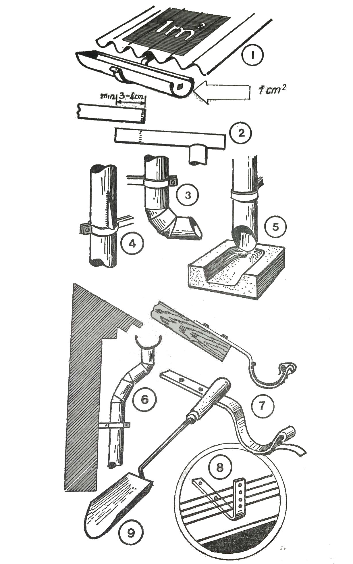
Archival drawing — roof-drainage system components.
Joints, fall and testing of the horizontal gutter
After installation, the gutter should be tested with water, particularly for low spots that retain water and can damage the sheet.
The source calls for annual painting of gutters and brackets except those made of tinned sheet. Elements are joined by riveting, folding and soldering. Folding the upper outside edge removes the sharp edge and stiffens elements 1–2 m long.
Riveted joints have at least 3–4 cm overlap. The element closer to the downpipe is placed underneath. Before riveting, the source applies a mixture of putty and red lead to contact surfaces; this historical material requires assessment under current safety rules.
The gutter falls towards the downpipe by 2–3 mm per linear metre. Bracket positions establish the fall, which is checked with a long straightedge and spirit level. The straightedge also reveals brackets that are too high or low.
Brackets have identical curves. The inner edge facing the wall is slightly higher to protect the wall from splashing. Brackets are nailed or screwed to the upper edges of the rafters. Metal tongues hold the gutter across its width while allowing longitudinal movement for thermal expansion.
Vertical downpipes
Water from the horizontal gutter flows through a purpose-made outlet into closed vertical pipes leading to a collector or the ground.
According to the source, the downpipe diameter is one half or three quarters of the horizontal gutter diameter. Pipes 2–3 m long are assembled with the upper pipe inserted 4–8 cm into the lower one. Wall clips secure them, and soldered stops above the clips prevent sliding.
Elbows are made from several pieces and changes of direction between straight portions should not exceed 30°. An expanded connecting piece avoids reducing the section at a bend.
The lower outlet directs water away from the wall and reduces its velocity. The source describes concrete discharge elements as inexpensive, adjustable and easy to clean.
Square gutters and pipes may suit modern buildings and can be recessed so only the front is visible, but damage may remain unnoticed until the wall becomes wet.
Snow and debris guards are also described. L-shaped supports are placed every 2–3 m and carry three or four longitudinal rows of 5–8 mm iron bars. They prevent leaves and branches reaching the gutter and sudden snow slides that could tear it away.
Cleaning and repairing damaged parts
The source links common damage with irregular maintenance. During leaf fall, gutters should be cleaned more frequently because decomposing leaves can attack paint and tin coatings. A hand tool may be shaped to match the gutter section.
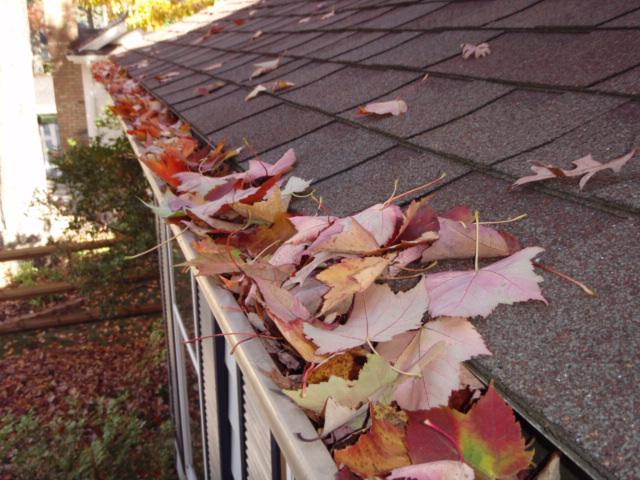
Illustration — accumulated leaves can obstruct drainage.
The source recommends painting untinned-sheet gutters in warm summer weather, then testing drainage with clean water. Where depressions hold water, the supporting brackets are raised.
Joints are resealed or resoldered as required; vertical pipes are described as cleanable with spirally wound wire.
Small holes are temporarily closed with putty. A strip of tinned sheet is soldered over larger holes, while larger damaged areas are cut out and patched externally. The patch is coated, riveted and overlaps by at least 1.5 cm on all sides. Epoxy or universal automotive filler is also mentioned.
Where a complete section is replaced, rivet heads are removed, the damaged section is moved sideways and withdrawn, and holes in the new section are marked from adjoining pieces before drilling, sealing, riveting and soldering.
When replacing a vertical section, everything above it must be secured against sliding. Aluminium parts are described as repairable by riveting and plastic parts by bonding and welding.
Gutter installation
Before installation, brackets are bent to shape. The source gives 80–100 cm spacing and attachment to the upper rafter edges with two size-80 nails or two 5 × 50 mm countersunk wood screws.
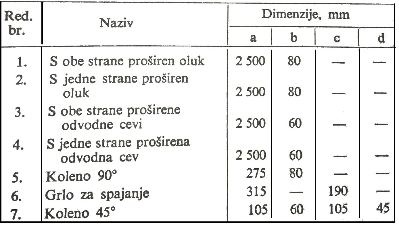
Archival table — system components and dimensions.
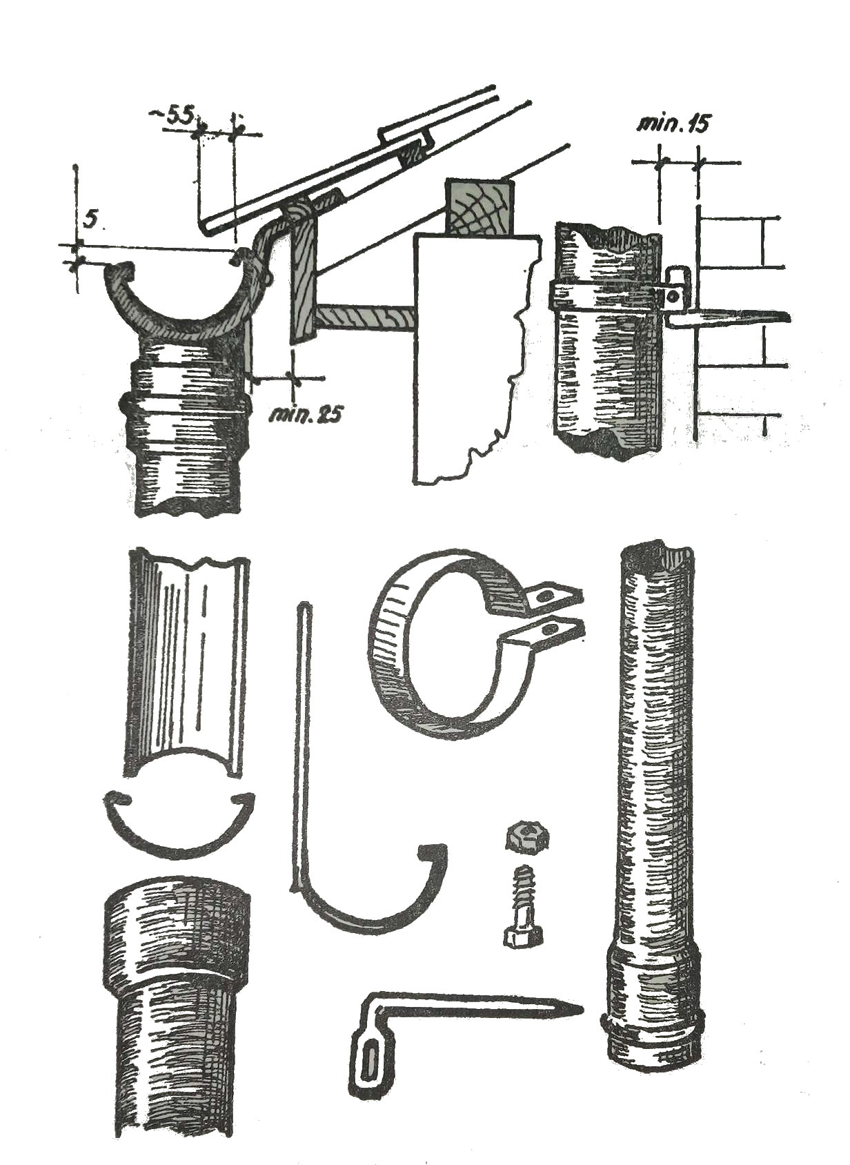
Archival drawing — horizontal and vertical element positions.
After bracket installation, bending sets a minimum fall of 2–3‰, or 2–3 mm per linear metre towards the downpipe. The outer edge is stated to be 5 mm lower than the inner edge, and the gap between the inner gutter edge and roof edge at least 25 mm.
The factory PVC sealing strip is checked before assembly. The source describes cleaning, washing with petrol and re-bonding a loose strip. Smoking and open flame are forbidden because of fire risk; current manufacturer instructions and rules for flammable solvents must govern modern work.
The unexpanded end of one element enters the expanded end of another in the direction of flow and a collar secures the joint. A 90° elbow and connector meet an unexpanded gutter end or internal end cap.
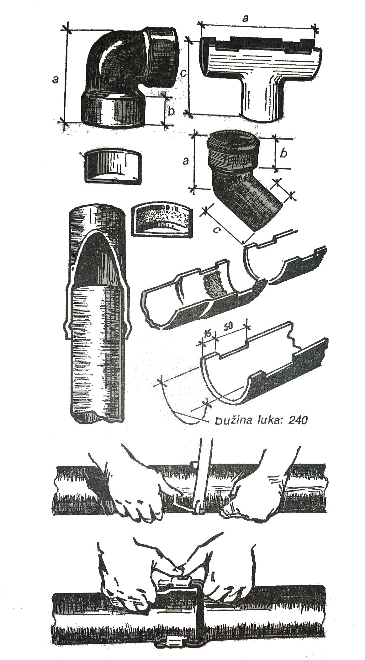
Archival drawing — joints, elbows and length adjustment.
Shorter pieces are sawn from elements expanded on one or both sides and the collar seat is filed. The lower edges of the filed openings are stated to be 240 mm apart along the gutter arc, checked with a paper strip.
Plastic downpipes
The source describes PVC downpipes in two sizes. A 90 mm pipe corresponds to sheet-metal designation 33 and a 110 mm pipe to designation 50.
Low weight, corrosion resistance and no need for painting or maintenance are cited as advantages. The historical claim that installation needs no special qualification must not replace a current safety and competence assessment.
Sizing uses the horizontal roof projection. The source assigns 60–65 m² to a 90 mm pipe and 110–130 m² to a 110 mm pipe; total roof area determines the number of downpipes.
Installing plastic downpipes
Downpipes may have a swan neck, using two 45° elbows, or be straight. The same elbows form the lower outlet.
A rubber ring seals expanded joints. Smooth pipe ends and the ring are lubricated with soapy water, assembled, then pulled back to leave 5–8 mm for thermal expansion. Oil is not used because the source says it attacks rubber.
After cutting, sharp edges are removed or chamfered at 30° over 5 mm so that the pipe end does not displace the seal.
The pipe is fixed to the wall at intervals no greater than 2 m with special fasteners, clips and tightening screws. The minimum wall clearance is 15 mm. The lower outlet is also clipped to the wall and a shaped concrete slab reduces the force of discharged water.
Installation safety
The source describes snow-retaining grids fitted alongside gutters on gable and hipped roofs. Wet snow sliding suddenly from a roof can cause serious injury and damage the gutter.
Regardless of the historical dimensions and methods in this text, roof access, fall protection, structural loading, work with tools and solvents, and protection of the area below must be planned in accordance with current regulations and the conditions of the specific building.