Archival expert content and serious risk: the article preserves the historical account of slope stability, symbols, formulas and diagrams from the original text. It is not a geotechnical study, excavation or embankment project, stability calculation, drainage plan, landslide assessment or work instructions. An unstable slope can suddenly bury people, buildings and roads; observed cracks, bulges, cloudy water, sudden subsidence or displacement should be treated as a reason for moving away from the danger zone and urgent professional evaluation.
Today, Savo Kusić is focused on wooden windows, wooden-aluminum windows, custom windows, doors and requests for quotation. This article remains as a technical archive and does not represent an offer of geotechnical design, supervision or execution of earthworks.
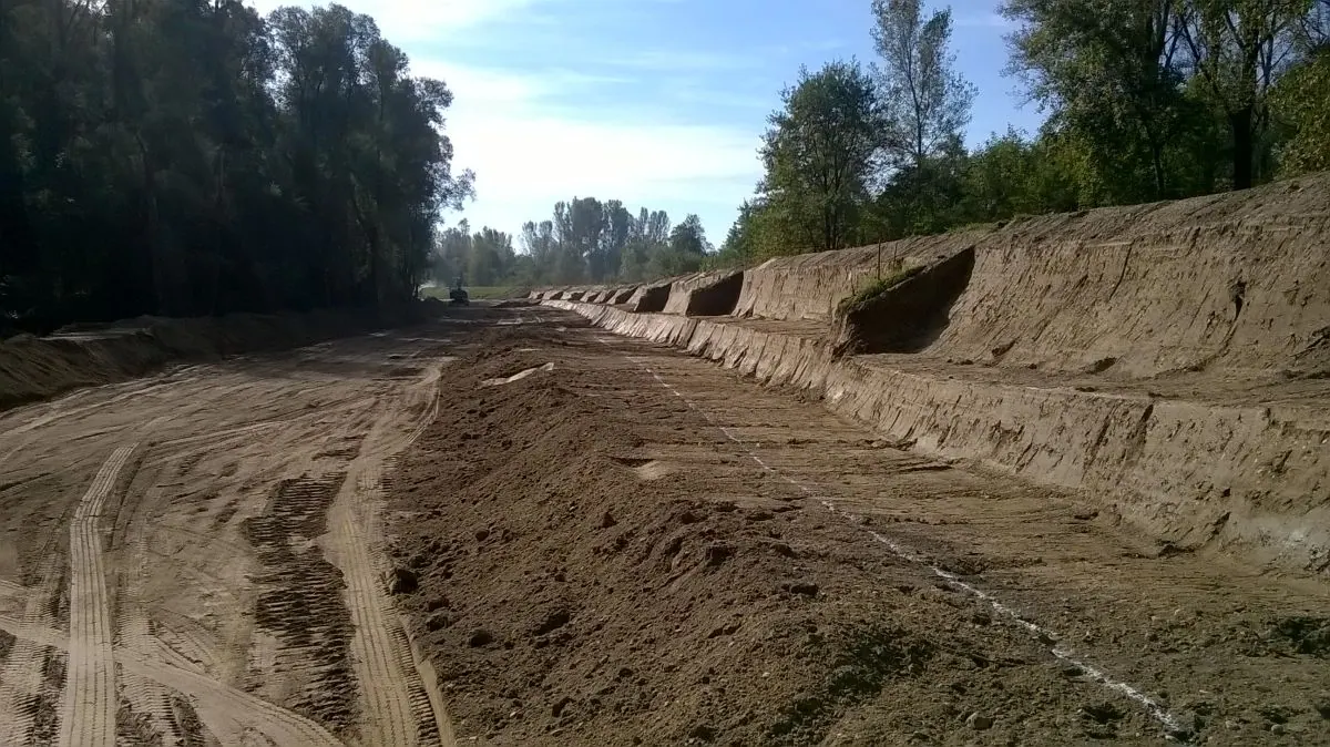
In the case of constructed earthworks such as cuts, embankments and canals, the final slopes are sometimes collapsed. And a natural slope, without artificial works, can move suddenly and with great force or very slowly. These phenomena have long been the subject of geological and geomechanical studies, with the aim of evaluating the stability from the physical characteristics of the soil and the conditions of each individual case.
Causes of movement of earth masses
The condition for the stability of any soil, whether it is an artificial earth object or a natural soil, is that there is a balance between external forces and the internal resistance of the soil. External forces are primarily the soil’s own weight, which is usually the only external force, followed by any other external load acting on the slope, permanent or moving. Internal resistance consists of cohesion and friction in cohesive soil, and only friction in cohesionless soil.

Sl. 1. Embankment slope in cohesionless soil
If we observe an embankment of height h made of completely cohesionless soil, for example dry compacted sand, we will determine that the slope of that embankment is inclined at an angle β to the horizontal (fig. 1). The size of the angle β depends on several factors such as grain size, grain shape and compaction. If we increase the embankment height h to h1, h2 etc. with the same cohesionless material of the same compaction, the angle β will not change, the embankment slope will remain at the same slope up to an unlimited height h. For a given cohesionless soil, the natural slope angle β is independent of the slope height h. The size of the angle β in cohesionless soil depends on the angle of internal soil friction φ and is assumed to be slightly smaller than it, or equal to it, β ≤ φ.

Sl. 2. Cut slope in cohesive soil
If we look at the cut made in cohesive soil, we will find that the slope of the cut is kept at a steeper gradient 1:m, i.e. at a larger angle β, because cohesion increases the internal resistance of cohesive soil and is not present in dry sand (fig. 2). In certain types of soil, such as dry loess, cohesion can increase the internal resistance to such an extent that the soil can be held with a vertically cut side, i.e. at an angle β = 90°. However, if we increase the height of the cut h in cohesive soil to h1, h2 etc., the angle of inclination of the cut slope β must be reduced in order to maintain stability. For each angle β of the cut slope in a given cohesive soil there is one critical height hc. If we exceed this height, the slope AB will not remain in equilibrium and will slide along a slip surface CD (fig. 3). The sliding occurred due to a disturbance in the balance between the external force, the own weight of the earth mass and the internal resistance, which was no longer sufficient to oppose the increased external force, i.e. the increased weight of the soil mass caused by the increase in the height of the slope h.

Sl. 3. Slope of cut in cohesive soil
From the above, it follows that the angle of the natural slope of the soil cannot be adopted as a constant value for the given soil, since its value under all other conditions depends on the height of the slope and decreases with the increase of this height. However, it is often adopted for slopes of small heights as a constant value, dependent on the angle of internal soil friction φ.
Disturbance of balance can also occur without increasing the height of the cut h, for example when the internal resistance of the soil decreases. The elements of internal resistance of cohesive soil, cohesion and friction, are highly variable and dependent on the amount of water in the soil. Therefore, in many cases, the cause of sliding is water saturation of cohesive soil, which can be so great that the soil is no longer able to support itself at any slope, but slides due to its own weight.

Sl. 4. Soil sliding due to formation of slip surfaces
There are various cases of soil sliding due to the reduction of internal resistance, of which we will mention here a few characteristic ones.
Formation of slip surfaces
If there is an impermeable layer of clay on a slope below the surface layer of permeable soil (Fig. 4a), or if there is an inclined interlayer of sand in the clay layer (Fig. 4b), into which atmospheric or surface water can reach (for example from a neglected drainage ditch), landslides can occur. A larger amount of water passes through the permeable layer to the clay layer, which it greatly wets, reducing its resistance on the surface, where the upper layer slips.
Disturbance of equilibrium caused by excavating a cut
Excavating a cut during the construction of railways and roads disturbs the previous state of equilibrium, because the soil exposed by the cut remains unsupported and tends to move downwards due to gravity. A state of equilibrium can be maintained if the internal resistance of the soil is large enough to counteract this tendency, which is also possible when the exposed soil consists of layers strongly inclined towards the cut.

Sl. 5. Sliding of terrain due to cutting in layered soil
However, if the layers of impervious and permeable soil are cut alternately (fig. 5), there is a possibility of leaching of the permeable soil and wetting of the impervious soil, on which slippage can occur.
Soil inhomogeneity
Thin layers of impermeable material in an embankment made of permeable soil, so-called clay lenses (fig. 6), can also cause sliding if a large amount of water reaches them and forms a slip surface.

Sl. 6. Case of embankment sliding due to inhomogeneous composition
Effect of frost
Under the influence of frost, water accumulates in the surface layer in the form of ice lenses. During thawing, the ice lenses turn into water, which supersaturates the soil to the depth of frost action, as a result of which it becomes a liquid mass and loses its stability.
This case occurs only with frost-dangerous soil and with longer duration of frost, because it takes a lot of time for the formation of ice lenses.
Lowering of the groundwater level
When the groundwater level is permanently lowered, for example due to undertaking work in the ground, drying of the soil occurs and, if it is clay that has a large swelling, cracks appear. Surface and atmospheric water enters them in larger quantities, moistening the soil and reducing its internal resistance, which can also lead to landslides.
There are many other cases of terrain sliding, so it can be considered that any coherent ground can, under certain circumstances, lose its internal resistance to a greater or lesser extent and, under the influence of external forces, be set in motion.
Cohesionless soil is stable as long as the slope angle is smaller than the internal friction angle of the soil. With this type of soil, sliding occurs only if the angle of slope is greater than the angle of internal friction. However, if an embankment is made of cohesionless material on clayey soil, the clayey soil may slide and the embankment collapse, so it is necessary to check the stability.
Assessment of earth-slope stability
Shape of the slip surface
The condition of balance between external forces and internal soil resistance was set by Coulomb with his equation
τ ≤ c + σ tgϕ
where τ is the soil shear stress, c is the cohesion, σ is the normal stress on the slip surface, ϕ is the angle of internal friction.
If the soil’s internal resistance, cohesion c and friction σ tgϕ are not sufficient to oppose the shear stress of the soil, sliding occurs on a slip surface inside the soil. There are different forms of slip surfaces, which depend on the physical properties of the soil, layering, water content, external load and other factors.
Depending on the position, the following typical cases of slippage are distinguished:

Sl. 7. Typical landslide cases
a) Sliding of the vertical sides of the cut. In the case of channels for water supply, sewage, etc., which are dug with vertical sides (fig. 7a), if the critical height hc, which depends on the physical properties of the soil, is exceeded, sliding occurs on the surface ADC. These slides are usually not along the entire length of the channel, but are localized, which is explained by the uneven shear strength of the soil.
b) Partial slope slips (fig. 7b). These slips often appear in the spring on the cuttings of railroad tracks and roads and are the result of oversaturation of the soil with water.
c) Slope sliding at the foot (fig. 7c). It is the sliding of the entire cut or embankment slope to the foot C.
d) Sub-toe failure of the slope (fig. 7d). It is the sliding of the entire cut or embankment slope and the soil below the slope toe. This sliding is also called base failure or Swedish slip, after the Swedes who first described it.
Regarding the shape of the slip surface, it can only be argued that the slip surface in cohesive soil is not a straight surface, but rather a curved surface. Certain authors adopt a circular arc (Fellenius), a logarithmic spiral (Rendulić) or a combination of these curved lines (Brinch Hansen) as the shape of the slip surface.
Effect of seepage on slope stability
If there is external water with a level of N1 (fig. 8) in front of the slope, a flow of water occurs in the soil behind the slope, which causes an internal pressure of water in the pores, as a result of which the friction between solid particles decreases and the shear stress in the soil increases.
If the water level N1 in front of the slope is constant, the water column H*γW causes water pressure in the soil pores, which reduces the friction between solid particles, as a result of which the danger of slope sliding increases. However, when the N1 level is constant, the pressure of the water column H*γW pushes the solid particles towards the interior of the soil, due to which the danger of slope sliding is reduced to some extent. In this case, with a constant water level N1 in front of the slope, there is a danger of the downstream slope sliding, because seepage in the soil causes solid particles to be pushed towards the outer side of the downstream slope.

Sl. 8. The effect of filtration on the stability of the soil slope
If the external water level drops sharply from N1 to N2, then the stability of the upstream slope is threatened. In this case, the internal pore water flows towards the outer side of the upstream slope, pushing the solid particles towards that side.
Because of all this, if the soil slope is submerged in water, the effect of seepage should also be taken into account when testing the stability of the slope.
The effect of seepage in the soil depends on several factors, the most important of which are permeability of the soil, hydrostatic pressure of the external water, rate of decline of the external water level and homogeneity of the soil.
If we assume that the embankment in fig. 8 is a homogeneous isotropic mass, under the effect of hydrostatic pressure of external water at level N1, water will flow through the pores of the embankment towards the downstream slope, whereby the groundwater level in the embankment will decrease with the flow-path length. If we introduce piezometer pipes AA’, BB’ and CC’ into the embankment (Fig. 9), pore water under the effect of hydrostatic pressure will enter these pipes and rise to the level N1, which can be the same in all pipes, if the points A, B and C are so selected that the heights of the water column in the pipes are h1, h2 and h3.

Sl. 9. Equipotential lines and flow lines
If we denote by h the elevation of the water level N1 in relation to some arbitrarily chosen plane O-O, then the potential h for all 3 points, A, B and C is the same. The line connecting these three points is the equipotential line. Groundwater in the soil cannot flow along that line, but only in the direction of points with lower potential.
In a similar way, we can choose in the same mass the points D, E and F with a lower potential h ― Δh. The line connecting these three points is the equipotential line of the potential h ― Δh. Water flow from the point A of the equipotential line ABC to some infinitely close point D of the equipotential line DEF will exist in the direction of the largest hydraulic drop imax, i.e. in the direction of the smallest distance Δlmin = AD. This means that the line AD along which water flows is perpendicular to both equipotential lines, because
imax = Δh / Δlmin
where Δlmin is normal to both equipotential lines. Those normals to the equipotential lines are the directions of the water flow in the permeable mass and are called flow lines. The set of equipotential lines and flow lines, mutually perpendicular to each other, forms a flow net.
Flow nets have different shapes according to the permeability of the soil mass. The most common case is an embankment made of permeable soil on impermeable ground, that is, on ground that can be regarded as impermeable (fig. 10). In this case, if the external water level is constant, the flow lines are parabolic in their middle part.

Sl. 10. Flow network in a permeable embankment on impermeable soil
In the case of an upstream slope, the parabolas join the lines perpendicular to the slope, which represents the equipotential line, because at a constant level N1 water does not flow down the slope. With the downstream slope, the parabolas end tangentially to the slope, which is neither an equipotential line nor a current line. The surface of the impervious soil below the embankment is a streamline, because the water at the bottom of the embankment flows parallel to this surface. In the upper part, the flow network ends with a basic parabola called the seepage line, which represents the boundary of the soil under the action of filtration. Below this limit, the soil is under the effect of filtration due to the hydrostatic pressure of the external water H*γW, while there is no filtration in the soil above it. The seepage line is also called the saturation line, since it is assumed that the soil below it is completely saturated with water, while above it it is partially saturated.
Actual slope assessment must include investigation, stratification, strength parameters, groundwater and surface water, level changes, drainage, seismic, excavation or backfilling phases, adjacent structures, and temporary conditions. Excavation without proper protection and entering the zone of possible landslide is not safe based on the general text or the shape of the slope itself.