Important expert note: This is an archival educational text, not a current design specification, static calculation, proof of load capacity, or manufacturing and assembly instructions. The design of steel structures must include actual actions, connections, stability, fatigue, fire, corrosion and all other relevant conditions according to valid regulations and standards, with the responsibility of the authorized designer.
The design and construction of steel structures is not part of the current public offer of Savo Kusić. Today’s production focus consists of wooden windows, wood-aluminum windows and custom doors.
Steel structures have the common feature that they are generally made of hot-rolled steel. Connections are made with rivets, bolts or welding. These include steel structures for bridges, buildings, industry and mining, hydraulic engineering, masts, towers and tanks, and, in a broader sense, cranes, shipbuilding and boilers. The following sections focus on the basic concepts.
Materials
The main construction material for steel structures consists of rolled sections made from structural steels S235, S275, S355, S420 and S450. Depending on the standard, there are several types of structural steel, and the number in the designation most often indicates the steel’s yield strength. Several letter symbols are used; in this case, S denotes structural steel. The most common designations mentioned here are S, B (reinforcing steel) and Y (prestressing steel).
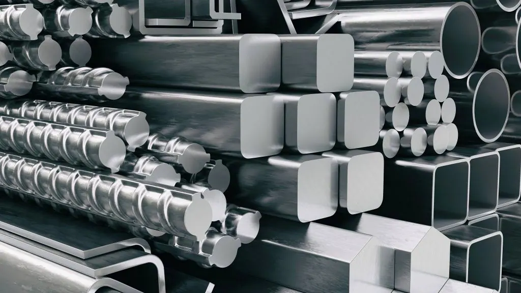
Rolled steel sections
There is a wide range of steel profiled supports and each has its own purpose, advantages and disadvantages.
- U-profiles
- I-profiles with narrow legs (IPE, IPN)
- I-profiles with wide legs (HEA, HEB, HEM, HD)
- Hollow profiles/boxes (round, square, rectangular)
- Sheet metal
- Cold-formed products (obtained by cold rolling of flat strip and twisting of flat strip)
Each of these profiles differs in shape, dimensions, purpose, etc. For example, there are over 20 different IPN profiles, which differ in dimensions; larger profiles can better withstand buckling (flexural and lateral-torsional), deflections, etc.
There are four classes of steel depending on whether they reach the yield point when the stress is increased, whether the analysis is plastic or elastic, what is the load capacity of the cross section, etc. where the first class is the best and the fourth is the worst. You can read more about the structure and strength of steel here.
Stress redistribution and load-bearing capacity under static loading
Bearing capacity. The dimensions of steel structures are determined so that significant permanent deformations are excluded. The bearing capacity, on the other hand, in many cases is not exhausted in any way when the highest comparative stress reaches the yield point - then the deformations grow much faster than the stresses. For structural steel, the same dependence as when yielding can be taken as the limit of Hooke’s law for general stress states. In the case of homogeneous stress states, which are equal at every place, no changes occur when the limit of proportionality is exceeded, except that the total deformations grow faster than the stress.
Stress redistribution in bending. For a beam in bending, the linear stress distribution according to Navier’s hypothesis applies as long as the edge stress σ=M/W does not exceed the proportional limit. The longitudinal strains are ε = ε(σ). This applies at least to small deflections. Beyond the proportional stress, stresses can increase only more slowly than the strains ε. Figure 1 shows the bending-stress distribution for a given stress–strain diagram and different values of edge strain. The proportional range, marked by a circle on each stress line, becomes progressively smaller as the edge strain increases. The edge stress is initially limited by σF. Only after very large deformations does the maximum stress rise above σF, making the effect of strain hardening in structural steel visible (case 5).
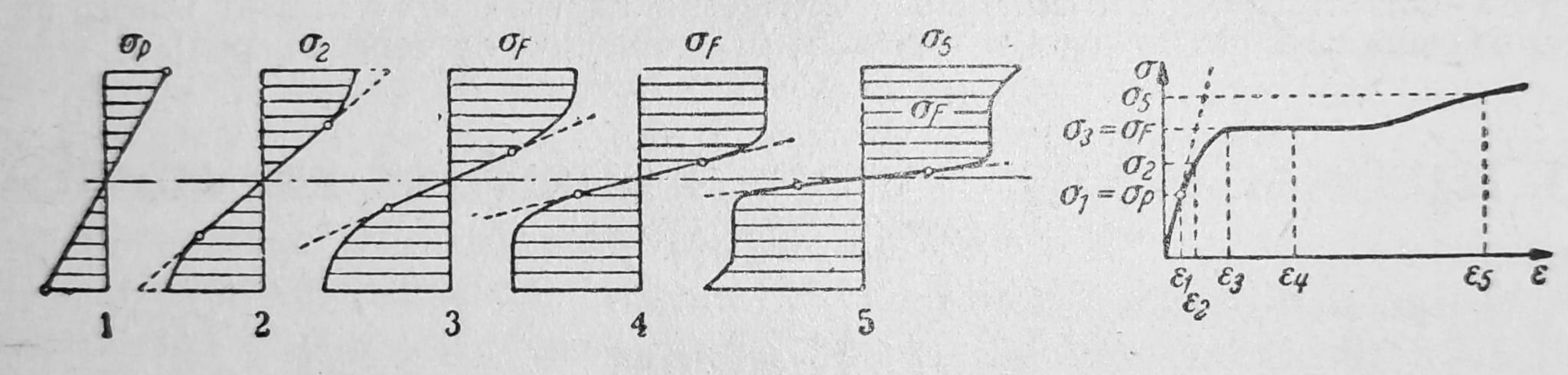
Fig. 1 — Stress redistribution during bending
Redistribution of stress peaks. The distribution of longitudinal stresses across the section through the centre of a hole in a tensioned drilled bar approximately corresponds to line 2 in Fig. 2. The stress peak σmax depends on the d/b ratio. It is generally about σmax = 2-3 σm, where σm = S/FM denotes the average tensile stress in the section weakened by the hole at FM. Figure 2 applies while the stress state remains below the P-limit. At higher loads, lower stresses than those given by the linear law are needed near the hole to produce a given strain. At the most highly stressed points, the stresses then increase more slowly rather than proportionally with S. At the limit, an approximately uniform distribution of longitudinal stress σm = σf is obtained across the entire section 2-2. Shear and transverse stresses are neglected. The redistribution of stress as the force S in the bar is increased slowly supports the usual approach for steel structures under static loading: neglect local stress peaks in design and compare only the average stress σm=S/Fm in the weakened section Fm with the permissible value.

Fig. 2
Load-bearing capacity design procedure
As the load increases, stress redistribution occurs within the section. Stresses shift from the most highly stressed parts of the section to the less highly stressed parts. As long as the deformations are not so large that they must be considered when establishing equilibrium, this process cannot change the magnitudes of S, M and other actions in statically determinate structures.
Continuous beams and frames: assuming Hooke’s law, a continuous beam of constant cross-section has the moment diagram shown under a in Fig. 3. The bending stresses are proportional to the bending moments M. If both loads are increased equally, the P-limit is first exceeded at the middle support B. The load-bearing limit is reached when the limiting moment MDF is also reached in the span. For a fixed-ended beam of constant symmetrical cross-section under a concentrated force (Fig. 4), moment redistribution exists from the outset. Exceeding the P-limit does not change the moment distribution. By contrast, under a uniformly distributed load (Fig. 5), moment redistribution reduces the fixing moment from -2/3 Mo to -1/2 Mo.
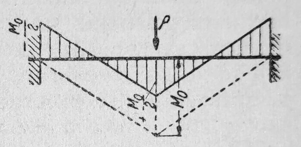
Fig. 4
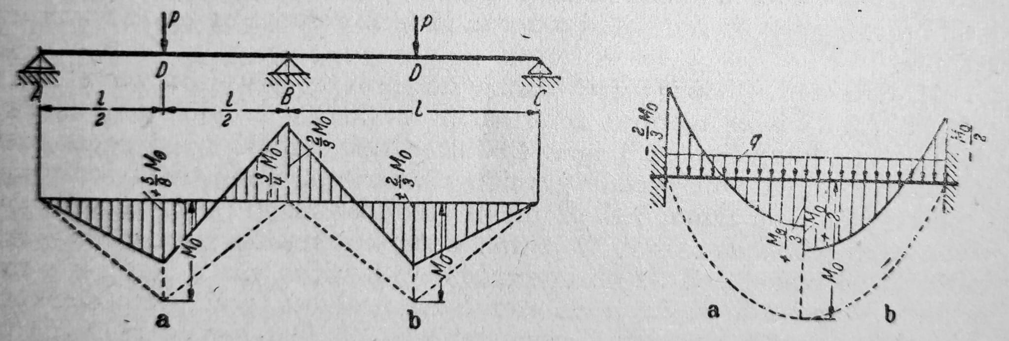
Figs. 3 and 5, respectively: bending moments: a) before and b) at the limit state after redistribution of forces; a) before and b) after moment redistribution
Lattice constructions: with internally statically indeterminate trusses, there are similar dependencies as with frame constructions. The secondary stresses, which are related to the nodes that are rigid in bending, can be neglected in the first approximation when evaluating the load capacity. Plasticized sections act similarly to joints, so that the static action of the girder under the ultimate load it can still carry is closer to that of an ideal truss with joints in the nodes. In the case of constructions with frequently repeated loads, in which fatigue strength phenomena should be taken into account, there are therefore considerable doubts against taking equalization of forces into account during dimensioning. On the contrary, it is of practical importance to conclude on the influence of the displacement of supports. Since the working strength of individual structural elements depends only on the stress limits, and not on the size of the total deformations, the displacements of the supports have no effect on the bearing capacity.
Alternating loading: the assumption of a constant load case is rarely realised. Bridge girders are subject to varying load states. Simplifying assumptions about forces and stress distribution in individual structural members are common in practical work with steel structures and, according to the preceding discussion, are justified under ordinary circumstances. This applies particularly to neglecting local stress peaks. The load-bearing-capacity design method cannot be recommended for dynamic fatigue loading. It is therefore limited to predominantly static loading, especially in building structures. In other cases where fatigue must be considered, significant deformations must be excluded and the theory of elasticity taken as the basis. A sufficiently large margin from the yield point should be maintained. The toughness of structural steel then provides some additional safety.
Alternating stress
Cold stretching and ageing: Figure 6 shows the stress–strain line of a round bar subjected to alternating tensile and compressive stresses. The individual loading stages are numbered in sequence. Recoverable elastic strains remain proportional to stress even after large extensions. When the sign of the stress changes, the P-limit almost completely disappears. The elastic properties of structural steel drawn in the cold state therefore do not coincide with the original values. Depending on the previous processing, substantial differences may occur.
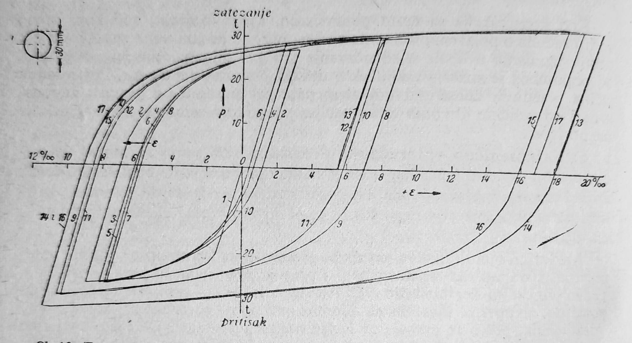
Fig. 6
Along with that come the signs of aging. This term includes all changes in properties that occur over time without external influence. Stretch aging can be observed after permanent deformation by cold stretching. If permanently stretched test specimens are left for some time without load at room temperature, the tensile strength and, to a lesser extent, the tearing strength rise above the original value, while the elongation at break decreases (Fig. 7). The aging process lasts for days, but is reduced to a few hours or just minutes, if the structural steel is heated to about 300 oC. It should also be mentioned that stretching aging occurs simultaneously with stretching, if this happens at temp. 200 – 400 oC, i.e. in the blue glow area.
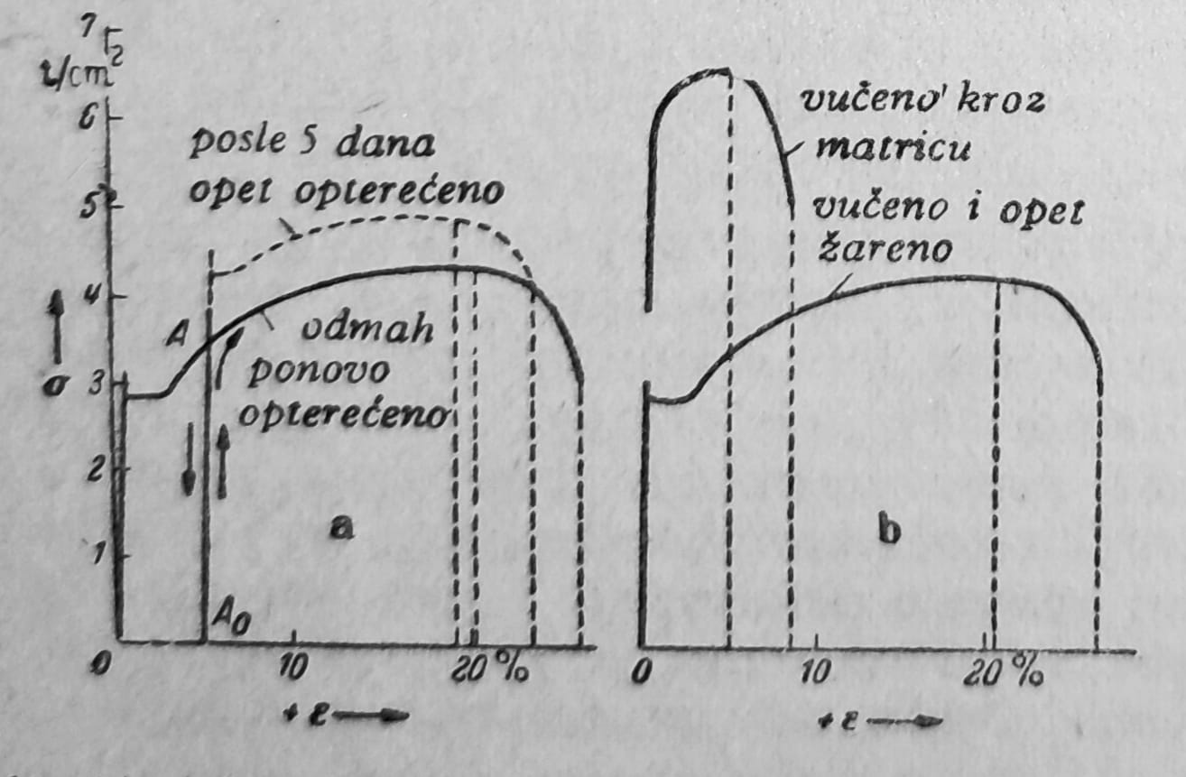
Fig. 7 — a) stress–strain line of a bar loaded twice; b) stress–strain line of a cold-stretched bar
Aftereffect and hysteresis: In a completely elastic material, the stress and deformation states have a unique reciprocal relationship, so that particular stresses always correspond to the same deformations and vice versa. For a given law of elasticity, deformation does not depend on the time elapsed since loading or on the manner of loading. Deviations from purely elastic behaviour may be described at two levels of approximation: in the elastic range they are small and may be neglected in a first approximation. Precise measurements can nevertheless detect them, particularly at stresses close to the elastic limit. Strain is not solely a function of stress: in a closed load cycle and at the same stress, it is always slightly smaller during unloading than during loading. This departure from complete elasticity—the difference between the corresponding strains at the same stresses—is called elastic hysteresis. If the load cycle is repeated, a closed hysteresis or damping loop develops at stresses that are not excessively high. Figure 8 shows damping loops for different levels of alternating load. The width of the loops increases sharply with stress. The area of a loop is proportional to the deformation work lost during each cycle and converted into heat. Deformation also varies with time and depends on the rate and manner of loading. The time-dependent component of deformation is called aftereffect. Hysteresis and aftereffect occur simultaneously. As a rule, they are of no practical significance for the structural steels used in steel construction at room temperature.
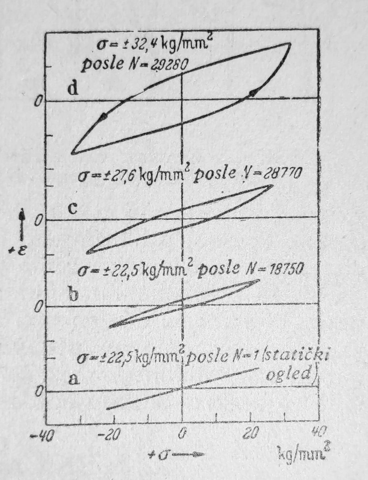
Fig. 8
Note for application: Historical material designations, assumptions, diagrams and procedures in the text should not be used as a substitute for current standards, specific product characteristics, calculation model and expert verification of the overall construction.