Today, Savo Kusić is focused on wooden windows, wood-aluminum windows, custom windows, doors and requests for quotation. This text remains as a geotechnical archive and is not an offer for laboratory testing, geotechnical design or earthworks.
There are several ways of determining the elements of internal soil resistance, cohesion and the angle of internal friction using laboratory tests, among which the direct shear test and the triaxial compression test are the most famous.
Direct shear test
The test is performed on an apparatus with a rectangular section of the A. Casagrande type or on a circular apparatus of the Hvorslev type. We will describe the experiment with the device of rectangular section, which is the most widely used. In both cases, the test is performed with an undisturbed sample, or with a disturbed sample at the yield point, in which case the test has a comparative value.
Direct-shear apparatus with a rectangular section (fig. 1)
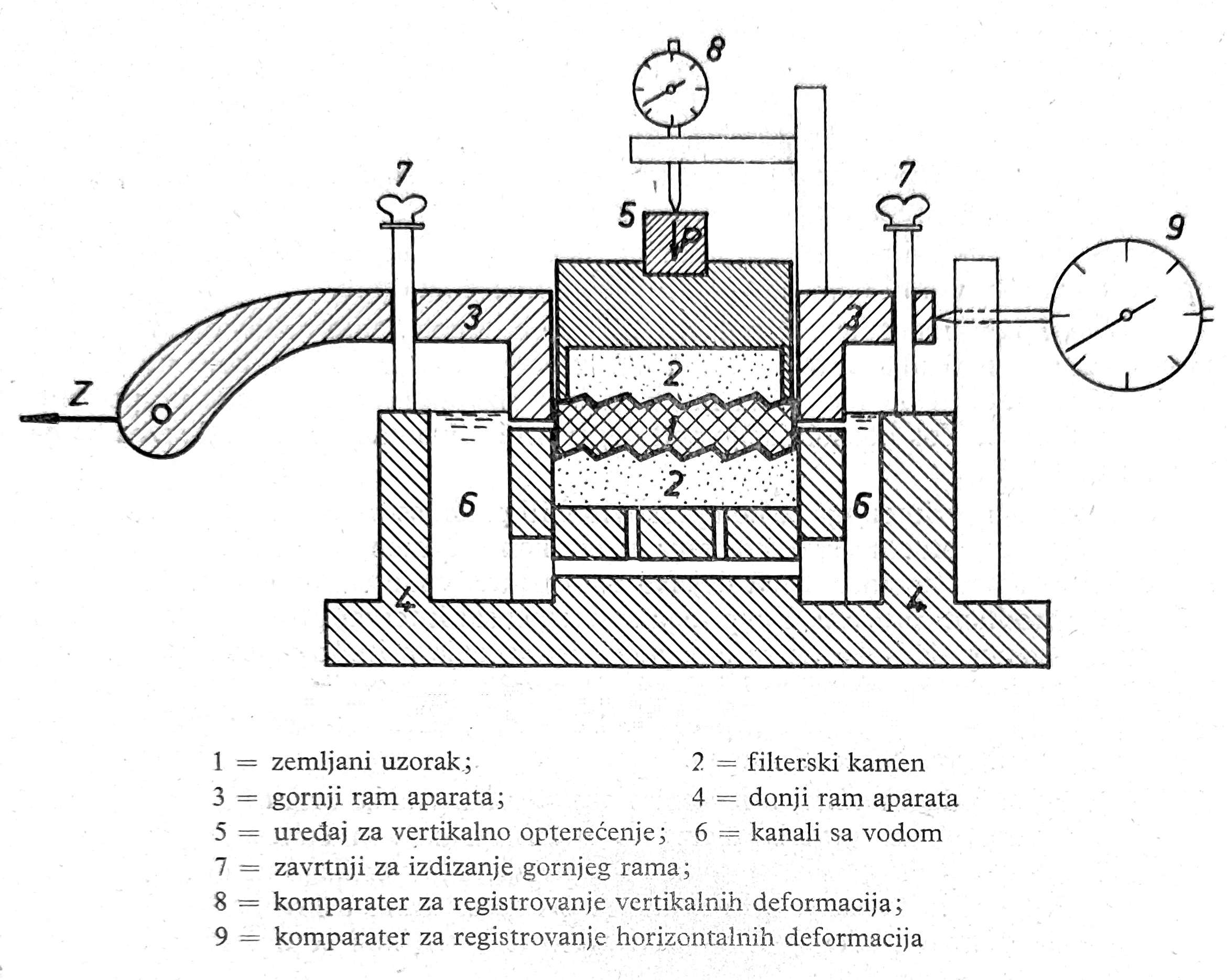
Fig. 1 Section of Casagrande’s direct shear apparatus
The apparatus consists of two parts, the upper and lower frame, where the lower one is static, while the upper one is movable and can be moved on the lower one under the influence of the horizontal force Z, which acts on the contact plane of the upper and lower frame.
The soil sample is placed in a steel rectangular ring, usually of the size 100 × 100 × 30 mm, or those dimensions when scraped accurately. Filter stones are placed over the top and bottom of the sample, and then everything is placed in the ring of the apparatus, which is then filled with water. A device for vertical loading is placed on the sample. The upper filter stone is connected to the system of vertical loading of the sample, while the lower one is connected to water channels, by means of which the sample can be kept in a saturated state during the test, in order to exclude apparent cohesion.
In order to exclude friction on the contact surfaces between the upper and lower frame, there are devices with the upper frame screwed, by means of which the upper frame moves under the effect of horizontal shearing force. In addition, the contact surfaces of the upper and lower frame are coated with petroleum jelly. A further 2 comparators are included in the device for registering vertical and horizontal deformations.
Conducting a direct shear test
There are mainly 2 types of direct shear test: fast and slow test. The fast test consists in loading the sample with a certain vertical pressure, which usually amounts to 0,50, after being introduced into the apparatus; 1,0; 2,0; 3,0 and 4,0 kp/cm2, wait for consolidation, which is assumed to have been achieved if settlement during 24 hours is Δh ≤ 0,02 mm, and then apply a horizontal shear force Z, size 1/20 or 1/40 part of the vertical force P, which increases every minute by the same value until soil failure. During the application of the horizontal shearing force, the course of movement of the upper frame is constantly monitored by reading on the comparator and the horizontal deformations are recorded in the log immediately before each new load. The moment, in which the comparator shows a sudden movement, is taken as soil failure.
The rapid test is applied to clayey soils, whose natural consolidation under a new load is slow and corresponds to this method of performing the test.
The slow test is performed in a similar way as before with the only difference that the horizontal shear force increases in a longer time interval, which can be 2, 5 and 15 minutes or until consolidation, i.e. until the horizontal deformations become completely insignificant. The course of consolidation under the effect of horizontal force is monitored on the comparator 9 (fig. 1).
The slow test is applied to sandy or silty soil, where if the horizontal shear force increases in a short time interval, the shearing of the sample in the apparatus would accelerate due to the effect of excess pore-water pressure, which would not correspond to a natural process. Therefore, the time interval increases with the fineness of the unbound soil particles, so as to enable equalization of the water pressure in the soil pores with the external water pressure. This equalization is achieved by leaving enough time under the effect of each level of horizontal load, so that the excess water in the pores is forced out through the filter stone.
In addition to the above tests, in certain cases a quick test without consolidation under vertical load is performed, i.e. the horizontal shear force is applied immediately after introducing the sample into the apparatus and loading it with a vertical load. However, this method of execution is applied under special conditions, such as the case of a freshly installed embankment made of clay soil, which is loaded immediately after filling without prior compaction.
Determination of the angle of internal friction and cohesion
Based on the test results, the shear stress is calculated
τ=Z/A in kp/cm²,
which is obtained from the shear force Z in kp at the moment of failure and the cross-sectional area of the sample A in cm². The test is done with 3 to 4 apparatus loaded with different normal pressure σ=P/A in kp/cm² where P is the vertical load of the sample in kp. The following values of normal pressures are usually taken: 1,0; 2,0; 3,0 and 4,0 kp/cm².
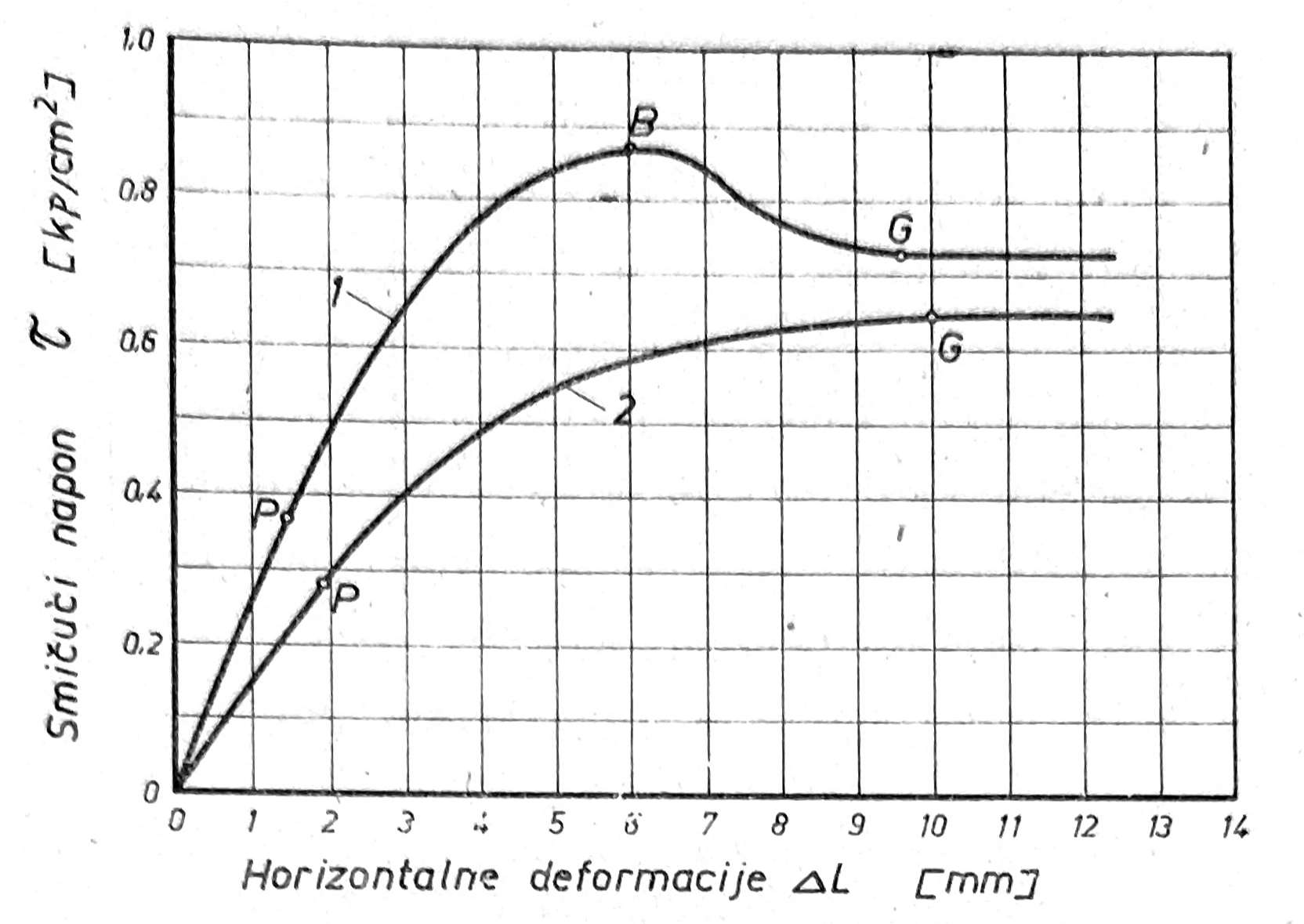
Fig. 2. Diagram of horizontal deformations
Based on the diagram of the elements of internal friction, two types of diagrams 1 and the diagram of horizontal deformations (fig. 2) are obtained.
The diagram of horizontal deformations is obtained by applying the horizontal displacement ΔL in mm of the upper frame of the device to the lower one, obtained by reading the comparator 9, on the abscissa axis, and the corresponding shear stress τ in kp/cm² on the ordinate axis (fig. 2).
Depending on the compaction of the soil, the diagram 1 for compacted and the diagram 2 for loose material is obtained.
For a compacted material, the shear stress τ increases initially rather sharply in relation to the horizontal displacement ΔL to the limit of proportionality P, then more slowly, while the curve of the diagram 1 increases and reaches the maximum height B, after which the diagram decreases over a certain length, to finally reach the horizontal flow. The zone of straight-line climbing of the horizontal deformation diagram, in which the increase in shear stress is proportional to the increase in deformation, is assumed to be the area of elastic deformation. Beyond the limit P, the increase in shear stress decreases according to the increase in deformations ΔL to the highest point B of the diagram. In this zone, the material begins to “flow” and it is adopted as an area of plastic deformation. The highest point B of the diagram 1 represents the maximum shear stress max τ, and it is assumed that soil fracture occurs at this point, i.e. that point B is the breaking point. Beyond point B, the material is in a liquid state, the shear strength decreases, and it is assumed that in this zone, where the connection between the particles is broken, there is only sliding resistance that opposes the horizontal shear force. The point G where the diagram 1 turns to the horizontal direction is adopted as the sliding limit.
The shear stress at the failure limit B is called the shear strength or pure shear strength τf, while the shear stress at the yield limit G is called the slip strength τg.
For loose material, the horizontal displacement diagram also has an elastic region with proportionality limit P, but downstream is a plastic region up to the slip limit G, i.e. the maximum shear stress is equal to the limit strength, slip (τ=τg), beyond which the liquid state of the material.
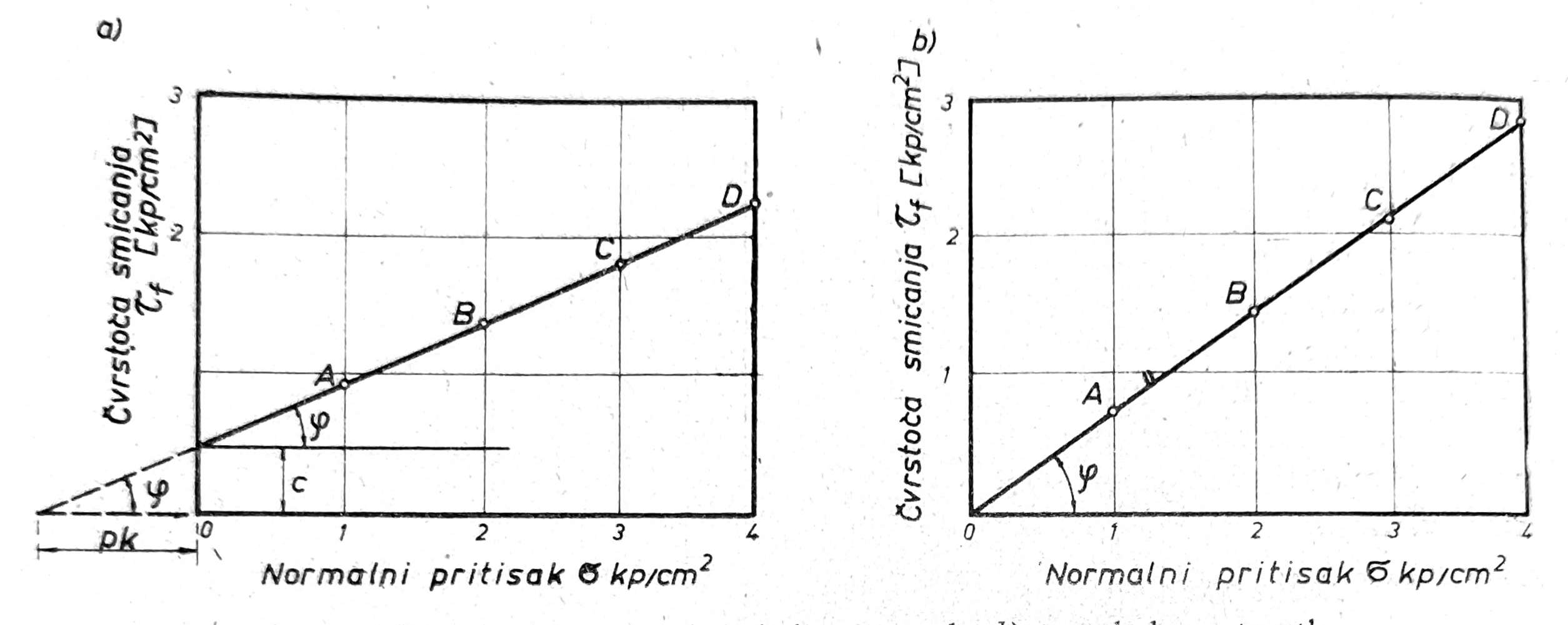
Fig. 3. Shear diagram, a) for cohesive soils, b) for cohesionless soils
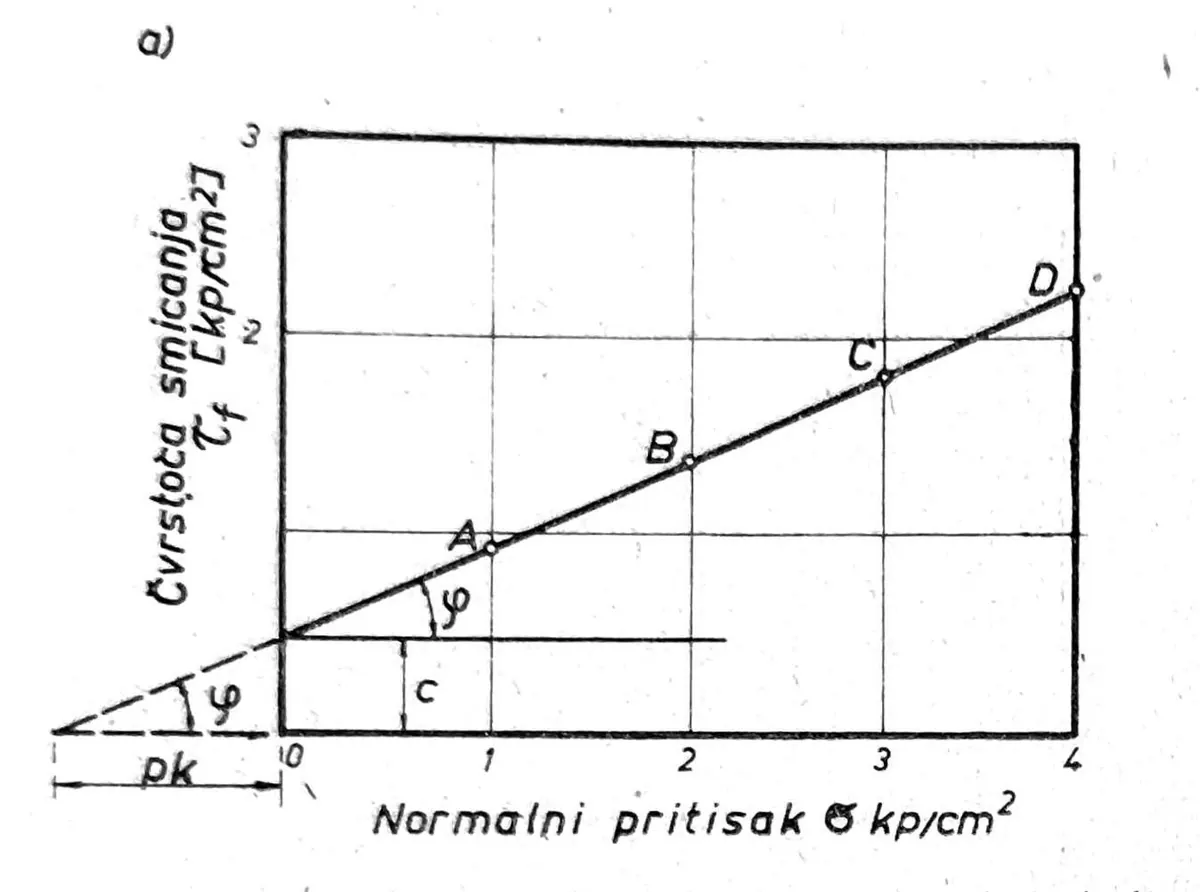
The shear diagram is obtained when the normal pressure σ in kp/cm2 is applied to the abscissa axis, and the corresponding shear strength τf in kp/cm2 is applied to the ordinate axis, whereby both of these values are applied in the same ratio (fig. 3). Since the shear strength τf of the soil increases with the normal pressure σ, for different pressures σ1 points A, B, C, and D will be obtained, which represent the corresponding shear strengths.
To obtain individual points A, B, C and D on the diagram 3 for cohesive soils (fig. 3a), the sliding strength _τ_g is adopted. However, in the case of clay soil, the material begins to flow long before the slip limit G is reached, so there is a tendency to adopt the shear strength at the limit of proportionality P to determine the cohesion c and the angle of internal friction of the soil, but since it is relatively small, the shear strength is often adopted for which the deformation ΔL on the diagram 2 is twice the deformation at the previous stage loads in the apparatus. This strength is somewhere between the border of P and B, or G (fig. 2).
By joining points A, B, C and D on diagram 76a, a shear diagram is obtained, which is a straight line in successful tests. By extending the diagram to the intersection with the ordinate axis, for σ = 0, it is obtained based on the Coulomb equation τf = c+σ tgϕ that τf = c = soil cohesion, while the inclination of the diagram to the horizontal gives the angle of internal friction. By extending the shear diagram on the other side of the ordinate axis, the stress due to cohesion pk is obtained on the abscissa axis, when the magnitude of cohesion c is expressed as the equivalent of frictional resistance:
c = pk tgϕ, whence pk = c/tgϕ
For cohesionless soils, such as sand, the diagram in fig. 3b, which passes through the coordinate origin, since for σ = 0 we get τ = 0. However, if the sand is fine-grained and wet, a diagram similar to the one in fig. 3a, with a smaller cohesion c, which represents the apparent cohesion. In that case, the stress pk on the extended abscissa axis on the other side of the coordinate origin represents the capillary voltage.
It should be noted that the determination of soil cohesion and friction by direct shear testing has several disadvantages, the most important of which are that soil failure occurs on a predetermined shear surface and not on the surface of least shear resistance, that during shearing of the sample in the apparatus, the shear surface is reduced due to the movement of the upper frame on the lower one, then that the deformations of the sample during shearing can only be monitored over a short length, so that the sliding resistance behind the fracture limit cannot be controlled to a sufficient extent, especially in the case of soft soil when shearing deformations are large, etc.
Triaxial compression test
The test is performed on a triaxial apparatus, which has different designs, but all of them are based on the same principle, which is as follows. The undisturbed sample in cylindrical form is placed vertically on the stand and exposed to the lateral pressure of the confining fluid from all sides and then to the vertical pressure, which gradually increases, until fracture of the sample is caused on the surface of least shear resistance. Based on the shear strength at break, the cohesion and the angle of internal friction of the soil are calculated.
Description of the triaxial apparatus
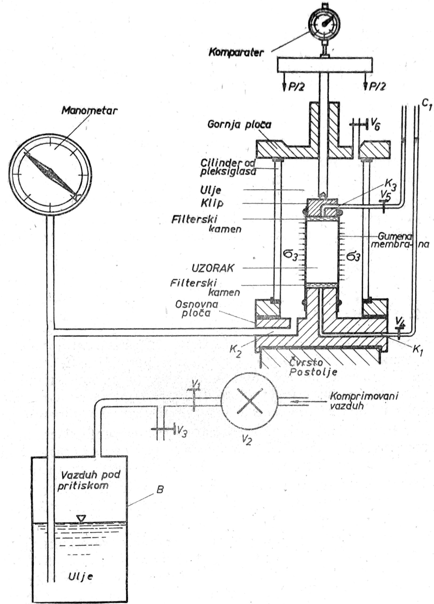
Fig. 4. Triaxial apparatus
The triaxial apparatus (fig. 4) consists in the lower part of the base plate of the chamber, on which the sample stand rests, and in the upper part of the piston for vertical loading of the sample and the upper plate that closes the chamber. The most common sample dimensions are diameter ϕ=36 mm, height h=2,2-2,5_ϕ_. Chamber diameter is D=135mm, height H = 180 mm. From the center of the sample stand, a narrow tube K1 starts for draining the sample from the bottom, which receives water from the sample through a porous plate and drains it outside the chamber into a vertical glass tube C1. If the test is performed without draining the sample, this channel serves to measure the water pressure in the pores. In the bronze base of the chamber there is a channel K2 for the supply of confining fluid in order to fill the chamber and achieve lateral pressure in the chamber on the sample.
Through the top plate of the chamber passes the piston rod for loading the sample. The sample in the chamber is surrounded by a rubber membrane, which is extended at both ends and is connected to the piston and the base by means of rubber rings. In the middle of the piston there is a channel K3 for draining the sample from the upper side.
From the sides, the chamber is hermetically closed with a plexiglass cylinder that is fixed to the upper and lower plates of the chamber via rubber rings.
The chamber is placed on a solid base. The normal loading of the sample is done via a lever with weights, the ratio of which is most often 1: 10. The system for achieving lateral pressure on the sample in the chamber consists of a bottle with confining fluid B, which is brought into the chamber by means of a tube, a manometer for measuring air pressure and a bottle with compressed air. A comparator is placed above the piston for loading the sample to measure the settlement of the sample under load.
The lateral pressure of the confining fluid in the chamber can be adjusted at will using the air pressure in the bottle B, through the valves V1 and V2. This pressure causes horizontal stresses in the sample σ2 and σ3, which due to the circular section of the sample are equalized σ2 = σ3.
The confining fluid can be distilled water or oil, which is preferred for better sealing, since water can pass through the screws. Under the influence of air pressure in bottle B, the confining fluid fills the chamber up to valve V6, which then closes. The vertical load of the sample P, which is transferred almost frictionlessly to the sample via the piston handle, divided by the cross-sectional area of the sample A gives the vertical stress σ1 = P/A
Conducting triaxial compression tests
For the test, the sample is trimmed in a separate apparatus to obtain a cylinder with a diameter of 36 mm and a height of 78 mm or 90 mm, on which filter stones are placed on the upper and lower sides and a rubber membrane is pulled on. Then the sample together with the filter stones is placed on the stand in the chamber, the ends of the rubber membrane are pulled over the stand and the loading piston and secured with rubber rings. According to the practice of certain laboratories, such as Prof. Skempton in London, drainage of the sample in the chamber during the test is accelerated by lining the sides of the sample with filter paper, which is placed before the rubber membrane is pulled on. When the sample is introduced into the apparatus and the Plexiglas cylinder is fixed in the upper and lower plates, the tests are carried out, which can be performed in several ways, such as the following:
-
Undrained tests. In these tests, draining of the sample is not allowed during the application of the lateral and vertical loads, with valves V4 and V5 closed.
-
Undrained tests with consolidation. During the application of lateral pressure, the sample is drained (valves V4 and V5 are open), while during the application of vertical pressure, drainage is not allowed (V4 and V5 are closed).
3_) Drained tests_. The sample is drained for the entire duration of the test (valves V4 and V5 are open), so that complete consolidation occurs and no excess pore-water pressure develops during the application of vertical pressure σ1. This test takes a long time, especially with poorly permeable soil, because the vertical load σ1 must be applied in a large number of small stages and consolidation must be waited for at each stage. In addition, the mentioned tests can be performed with saturated and partially saturated samples_._
Considering the possibilities mentioned above, triaxial compression tests can be performed in different variants and adjusted according to the type of soil under load conditions.
The apparatuses, procedures, units, values and patterns described are transmitted from historical sources. The text is not a geotechnical study, laboratory protocol, foundation project, proof of slope stability or excavation plan. The choice of sample and test method, state of drainage and consolidation, groundwater, load regime, seismic influences and excavation safety must be determined for the specific soil and facility, according to current regulations, with the appropriate laboratory and authorized geotechnical expert.