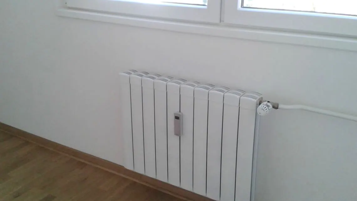
Safety note: This is an archival educational text from 2018, not a design or instructions for installing a heating system yourself. Calculation, equipment selection, installation, testing and commissioning should be entrusted to qualified designers and contractors, in accordance with current regulations and the manufacturer’s documentation.
A building envelope also affects the overall heating demand. See our wooden windows, wood-aluminium windows and services, or send a request for quotation.
Heating of larger apartments and family buildings is traditionalit is not the most pleasant winter pastime for those stoves. Heating on this way is unpleasant not only because it creates work about the maintenance of the stove, but also because it has to be prepared fuel, light the fire, clean the ashes, and with all this the apartment gets dirtier than usual due to work. In addition to these disadvantages, heating with stoves is neither aesthetic nor po evenness of the temperature distribution does not meet the requirementof modern housing. Starting from these facts, it is not surprising that not only in new buildings in societiesostrich property, but also in special family buildings today applies a central heating system.
Heating scheme and operating principle
Central heating device (fig. 1) consists of systems: boilers, heating elements and pipelines. The highest point of this of the system is an expansion vessel. The whole system is filled with water. If we burn in the boiler, the water is also heated due to less specific weight goes up, and hot water is replaced by water that has cooled down in the heating elements (therefore it has a higher specific weight). The water that flows upwards comes through the pipeline to the heater body is there, giving off its heat, cools and returns to boiler.
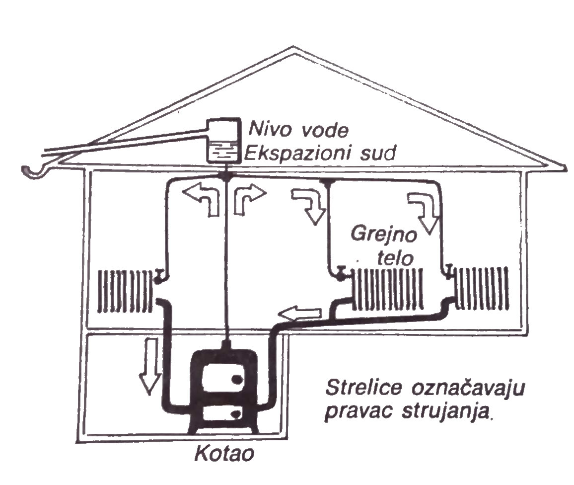
Figure 1 — Central-heating system.
Therefore, due to the difference in the specific gravity of cold and hot of water in the system creates one continuous closed flow which enables the supply of a certain amount of heat by heating bodies.
The force that enables the circulation of water due to the difference temperatures - especially when heating only on one level - is very small and therefore it is important to size the devices based on careful and accurate calculations. In practice, it often happens that devices, especially for smaller and individual stanovs, project quickly and based on data from experienceva. Undoubtedly, it can also be done this way sometimes successfully execute a central heating system, but the case is more common that it does not function flawlessly, and the resulting errors are already more difficult to correct later.
Therefore, we must not regret the effort to create the necessary calculations and projects, because it will certainly pay off. We must not lose sight of the fact that such a system should serve for a lifetime.
Calculating the required amount of heat
The first task in designing is to calculate the needon the amount of heat for heating the desired rooms. Required the amount of heat for heating matches its lossesoh Heat losses depend on the difference in external temperature and the temperature of the room to be heated, from the coefficient of the heat passage of those surfaces that bound the observed room as well as the size of these surfaces.
The calculation should be done separately for each surface with with different heat transfer coefficients and with differences in spexternal and internal temperatures. The sum of the thus obtained parciof results will give the total required amount of heat premises. (For those who are reluctant to do the calculations, note that only basic calculations are required for the calculation).
The required amount of heat is calculated using the formula:
Q=F * k (t_(b )- t_(k))
where are:
Q - the amount of heat lost by the room, kcal/hour;
F - surface (wall, window, door, floor, ceiling) through which heat passes, m²;
k - heat transfer coefficient for the observed surface, kcal/m²°C
t_(b )- desired internal room temperature, °C
t_(k) - external temperature of the observed surface, °C
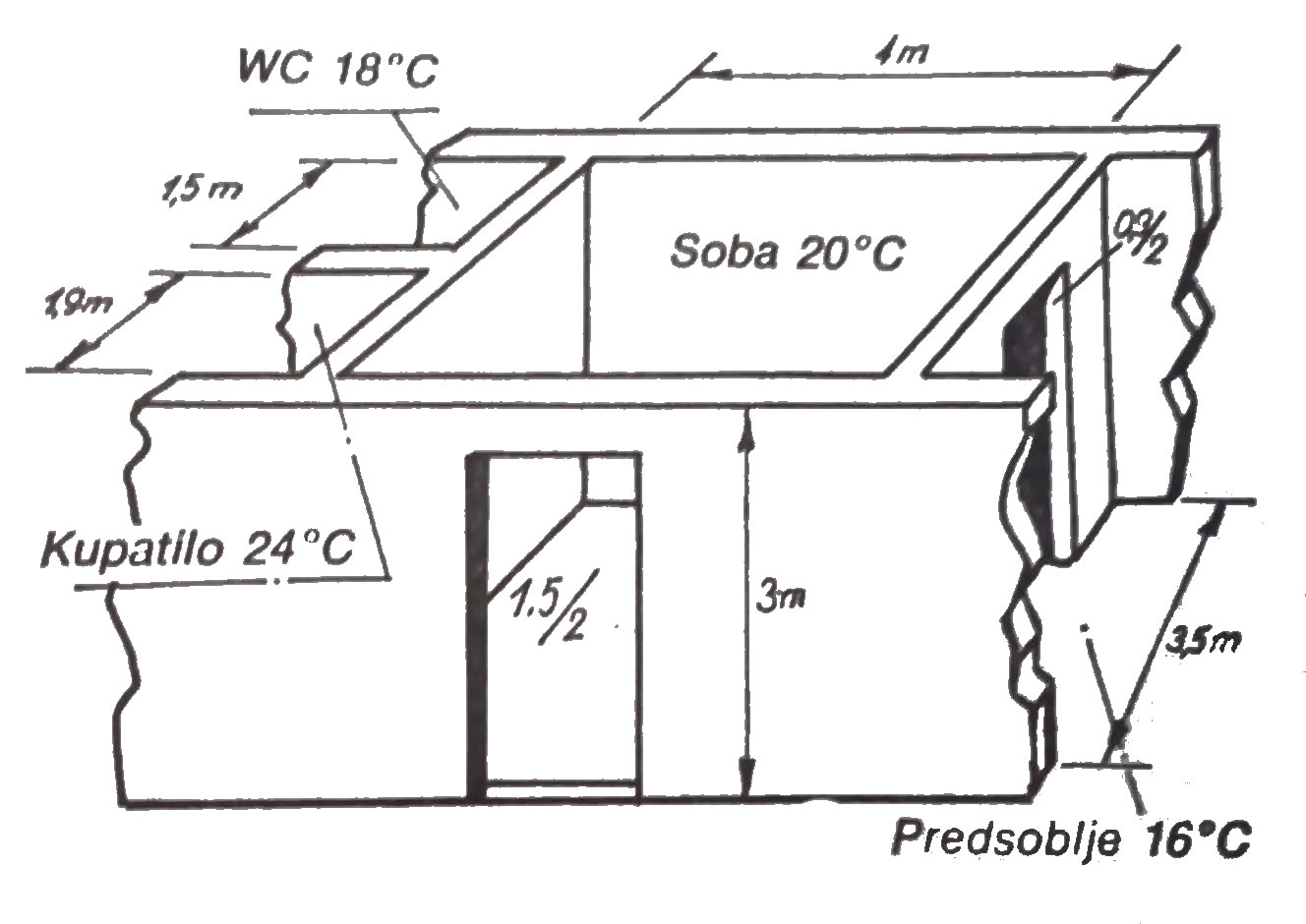
Figure 2 — Example of calculating the required heat.
Archival room-calculation example
For a better overview of the calculation flow, we will take a practical example. The task is to calculate the required quantity heat for the residential building from picture no. 2. The technical data are: partition walls made of porous bricks, dimension 10 cm, plastered on both sides, main wall thickness 38 cm plastered on both sides, single-glazed doors, rrozor double with a wooden frame. ceiling with wooden with beams on both sides covered with boards and above the ceiling closed attic, earth under the floor. Expected minimum external temperature - 20°C. The passage of heat through the outer window:
Area: F =1,5 x 2 = 3 m²
Heat transfer coefficient: k = 3,5
Temperature difference: t_(b) = +20°C, t_(k )= - 20°C, t_(b) - t_(k) = 20 - (-20) = 40°C
Q=3 x 3,5 x 40 = 420 kcal/hour
Heat passage through the outer main wall:
Area: F = 3 h 4 - window area = 12 - 3 = 9 m²
Q = 9 x 1,3 x 40 = 468 kcal/hour
The passage of heat through the door to the hall:
Area: F = 0,9 x 2 = 1,8 m²
k = 3
Temperature difference: t_(b) = 20°C; t_(k) =16°C, t_(b) - t_(k) = 20 - 16 = 4°C
Q =1,8 h 3 h 4 = 21,6 kcal/hour
Passage of heat through the wall towards the hall:
Area: F = 3 x 3,5 - door area = 10,5 - 1,8 = 8,7m²
k = 1,6
Temperature difference: t_(b) - t_(k) = 40°C
Q = 8,7 x 1,6 x 4 = 55,7 kcal/hour
Passage of heat through the wall towards the WC:
Area: F = 1,5 x 3 = 4,5m²
k = 1,6
Temperature difference: t_(b) - t_(k) = 2°C
Q = 4,5 h 1,6 h 2 = 14,2 kcal/hour
The passage of heat through the wall towards the bathroom:
Area: F = 1,9 x 3 = 5,7m²
k = 1,6
Temperature difference: t_(b )- t_(k) = 20 - (+24) = -4°C
In this case, the heat goes from the bathroom to the rooms, i.e. it is not a matter of loss of heat, but of gain and therefore this the value at the end should be deducted from the total required heat.
Q = 5,7 x 1,6 x (-4) = -36,5
There is no difference in temperature between individual rooms, ratherhowever, there is no transfer of heat, so there is no need for a fortune tellernati.
The passage of heat through the ceiling:
Area: F = 3,5 x 4 =15 m²
k = 1,5
Temperature difference: t_(b )- t_(k) = 20 - (-12) = 32°C
Q =15 h 1,5 x 32 = 720 kcaI/hour
The passage of heat through the floor:
Area: F = 15m²
k = 1,5
Temperature difference: t_(b )- t_(k )= 20 - (-2) = 22°C
Q = 15 x 1,5 x 22 = 495 kcal/hour
Total required heat:
420
468
21,6
55,7
14,2
720
495
2194,5 kcal/hour
The value obtained in this way should be increased with additions such as side of the world allowance, wind allowance and allowanceinterruption of heating.
Wind accessories:
Normal areas: with one external wall with an opening:
10% with multiple exterior walls with openings: 15%
Windy areas: with one external wall with opening:
20%, with multiple outer walls with openings: 25%.
Add-on to stop heating:
Expected interruption in heating from 8 - 12 hours per day: 15%.
Expected interruption in heating from 12 - 16 hours per day: 25%.
Supplement to the sides of the world
Northwest orientation: 5%.
North orientation: 10%.
The room in the example is located in an area with normal winds, it is oriented to the north and therefore obtained values should be added twice 10%, i.e. total 20%.
We will not count the warm-up break allowance, because it is less continuous.
2194,5
+438,9 (20%)
2633,4
The amount of heat received from the wall should be deducted from this value according to the bathroom:
2633,4
- 36,5
2596,9
Therefore, the required amount of heat to heat the room is Q = 2597 kcal/hour
System design
First of all, when designing, you should draw the base of the sides in scales 1:100. or if I possibly 1:50. Heating elements requiredbut should be placed under the window, and in rooms where there are no windows, next to the door that leads to the free space, or towards cooler rooms. This layout is because of possibly a longer pipeline, slightly more expensive than the scheduleheating elements along the inner walls, but the advantages are the flow of air and, in connection with that, the distribution of temperature, very importantit is not. (fig. 3)
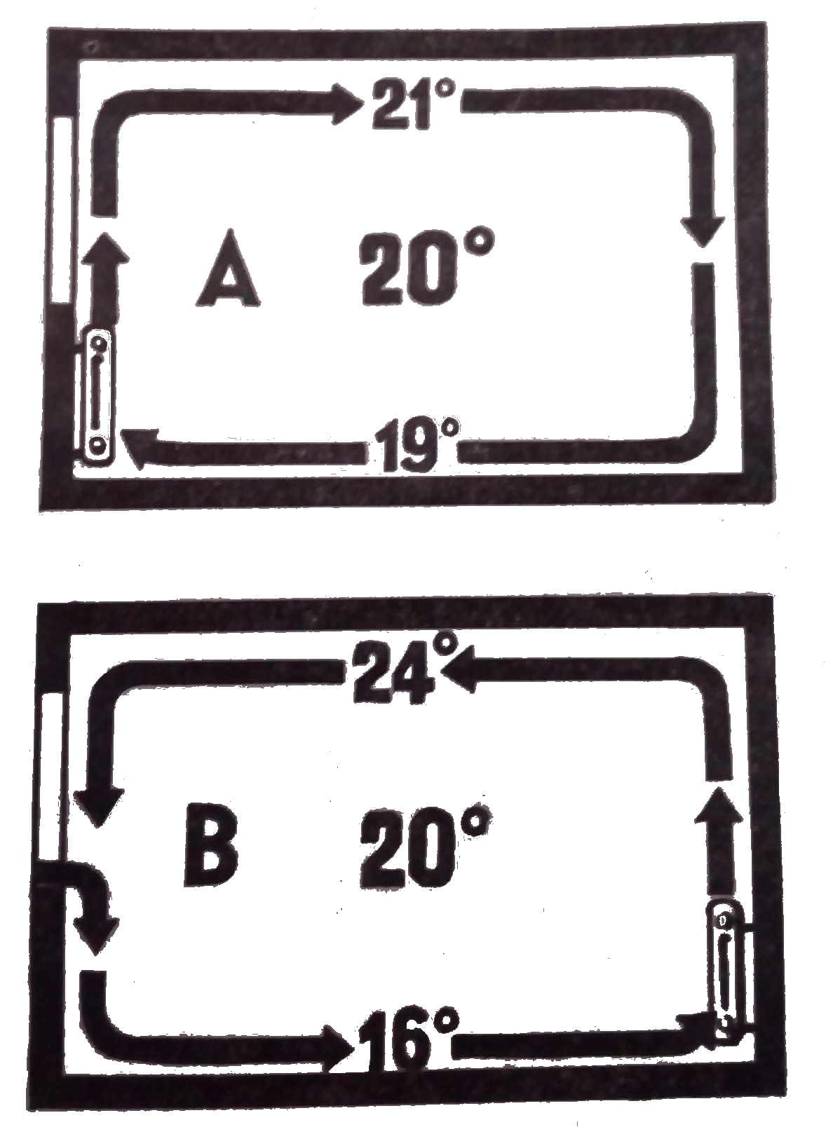
Figure 3 — Air flow around a heating element.
Selecting heating elements
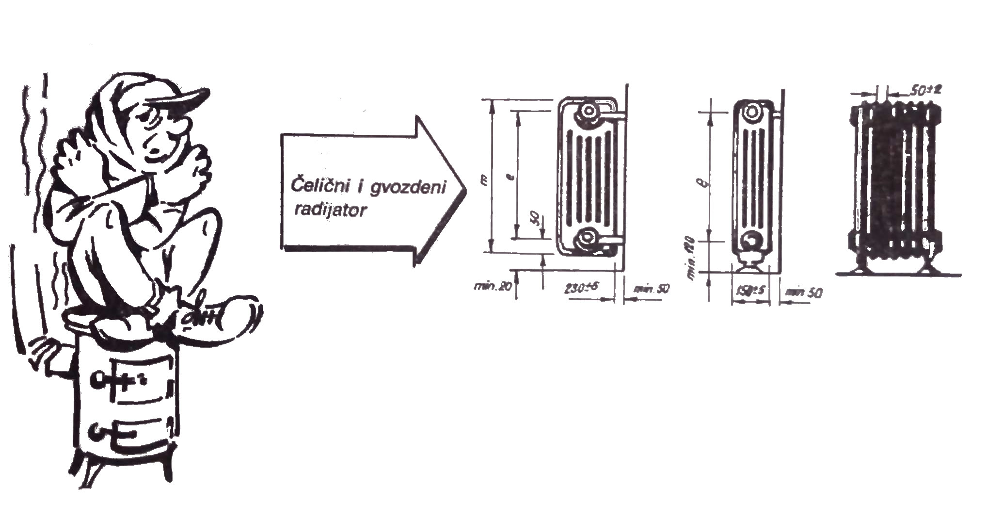
After designing, choose the type of heating elements and determineoutside the required heating surfaces. For hot water heating the most suitable heating elements are steel radiators. These radiators many are reluctant to use, allegedly because the water themit spoils and leaks quickly. However, this only happens with then when water is frequently and unjustifiably released from the system, or when, after draining the water, the radiator is left for a long time time without water. Under normal use, the service life of steel radiator is approximately the same as the lifetime of cast radiostora. Cast iron radiators are not the best for heating with hot water in the first place because they are very expensive, and also because they have a large own weight. In terms of thermal performance, both types of radiators are identical.
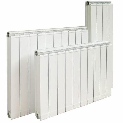
Aluminum radiators are among the most modern heating elements (Alutherm, Radal). The thermal characteristics of these radiators are very affordable, their own weight is low, they have a very beautiful and modern external appearance. Their connectionconnection is made with threaded flanges. When merging radiator, so as not to create a galvanic element in connection with that and corrosion, the heads and shafts of the screws should be insulated by the electriple insulator.
Joining radiator sections
Wide steel radiators should only be used when if the use of normal (of 150 mm) would result in a very long radiator. Steel radiators can be obtained commerciallywine with 5 - 10 -15 - 20 articles welded together. If if one radiator requires more than 20 articles, then it
we can extend it by a unit of 5 or possibly of 10 elementa by intermediate bolts for radiators of 5/4“ with left and right thread and sealant made of clingerite or centaur. Screw is recommendedlubricate with water-resistant grease with a boiling point above 100°C, or graphite oil. A specially made key is required for mounting the elements.
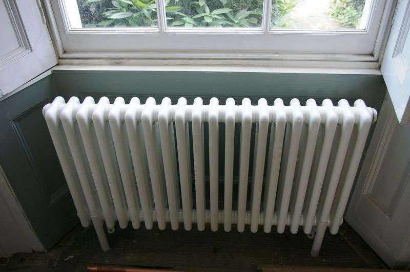
Cast iron radiators as well as old steel radiatorse productions are assembled by elements and fastened togetherscrews. If we buy used radiators, we must themshould be carefully inspected and checked before installation, especially component places of individual elements. Some are bestwith a sharp object (eg a three-edged scraper) check sthinner sheet, because the weakened sheet will be punctured due to the pressure so in this way we will save ourselves from further inconveniences.
Pressure testing
Radiators that we assembled ourselves, or second-hand radiatorsre, it must be examined before assembly. It will be tried anywayit is easier to do if we close one end of the radiator with plugslet’s put it on those plugs. Then we completely fill radiator with water and close one of the remaining openings with a threaded plug, and put a rubber on the other openinghose with pipe connection. The other end of the rubber hose let’s connect to the water supply network. If due to water pressureafter 5 -10 minutes we do not notice that the water network is workingjator is leaking, we can mount it. Where there is no water network, the pressure required from 2-3 and we can produce i with a hand pump.
We can place the radiators on legs or consoles, which are attached to the wall. The solution with consoles is better, because it does not prevent cleaning under the radiator, and it has a better esaunty look. To fix the console, you need to drill in the wallopening depth 10 - 12cm so that the sides of the opening are soralelne or that the opening widens towards the wall. Above opening at least two rows of bricks must remain undamaged. For workA jator of 20 elements needs two, and for a longer one - three consoles.
Heat source
The required heating surface of the boiler is determined based on total required heat of the building (apartment). We will get this size by adding the required amounts of heat for individual rooms. For smaller boilers, which are fired with coke or with better quality coal, it can practically be counted with 10.000 kcal/hour for 1 m² heating surfaces. Therefore, if divide the total required amount of heat by 10.000, then we will approximately get the required heating surface of the boiler. It is recommended, however, to take a boiler with a slightly higher performance from calculated.
The type of boiler is primarily determined by the type of fuel. For coke, small cast iron boilers are most suitable. For boilers made of steel are more suitable for burning with different fuelsand has a welded construction.
Small boilers usually have a heating surface of 1,5 m² (15.000 kcal/hour), 2,14 m² (22.000 kcal/hour) and 3.16 m² (32.000 kcal/hour). For the family building, which is given in picture no.4 as an example, 17.000 kcal/hour is needed roundedtotal heat. We chose coke for fuel. According to all given data requires a boiler with a heating surface from 2,14 m².
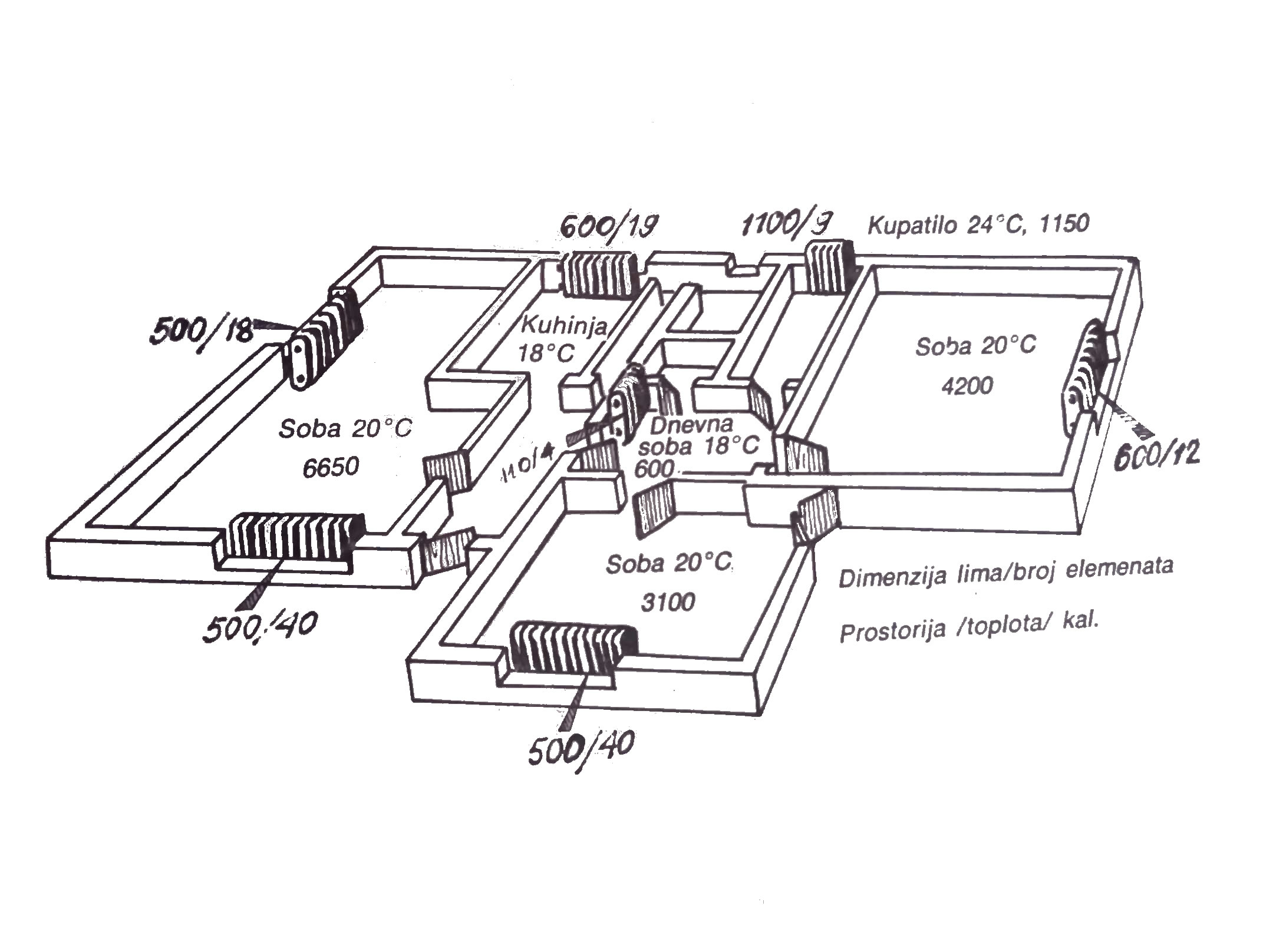
Figure 4 — Required heat for a family house.